Heat exchangers can be classified according to its construction as stated below.
1. Shell and tube heat exchangers
Shell and tube exchangers are the most commonly used heat exchangers in process plants today. The reasons for this are that shell and tube heat exchangers can operate on a wide range of operating temperature and pressure and It has well established procedure and availability of codes and standard for design and fabrication.
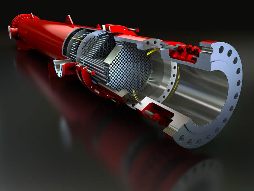
Below is a figure-1a showing important parts of a shell and tube heat exchanger. Basically it has a cylindrical shell around a nest of tubes generally called tube bundle. Tube bundles are made of many small diameter tubes which are hold at each end by holed plates called tube sheet.
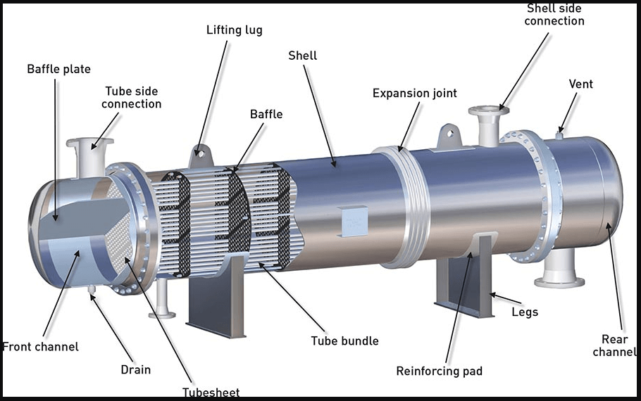
One fluid enters from the tube side connection and passes through the tubes; the other fluid enters the shell through shell side connection and passes through the cylindrical shell over the tubes exchanging heat with the other fluid.
Baffle plates are installed in tube side front channel to accommodate several passes on the tube side. Baffle plates are also installed inside shell perpendicular to the tubes to direct the fluid in the shell against the tubes. Baffles are used to give time for the fluid to exchange heat, to improve flow path and to have proper fluid velocity so that heat recovery can be increased. A working animation for the same is provided in below video link.
These exchangers are designed in accordance with Tubular exchanger Manufacturers association (TEMA). TEMA also specifies exchanger part types in a letter code which tells the designer what the exchanger looks like.
As per the TEMA standards, there are 3 important parts for shell & tube exchanger design. Those are
1. The front end
2. The shell
3. Rear end
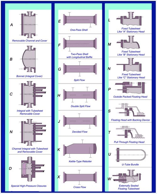
Above table from the TEMA standards (Fig-1b) explains the different possible configurations for each of the 3 broad parts. In exchanger datasheet exchanger type is mentioned in letters same as highlighted in below datasheet snap i.e BET. By referring standard TEMA figure given in figure 1.1 B means channel end will be – integral cover bonet, E means shell type will be one flow pass similarly T means rear end will be pull through flow head. So putting them all together the designer gets the configuration of the exchanger.
Shell and tube heat exchanger can further be divided into 4 major categories
A. Floating head shell and tube exchanger
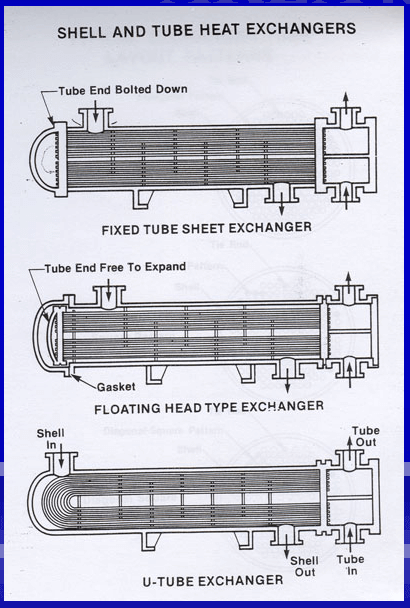
The floating head exchanger consists of a stationary tubesheet and one floating tube sheet. The tubes and tube sheets can expands freely to accommodate the thermal expansion. The floating tube sheet must be enclosed by a floating head cover. The channel head and shell cover arrangement are very convenient for inspection.
Floating head exchangers are used when the temperature of fluid involved in heat exchange creates expansion issues. Most heat exchangers are of this type.
B. U tube exchanger
Here the tubes can expand and contract freely but there is only one stationary tube sheet is required. For inspection of tubes in this type of exchangers the tube bundle has to be pulled out.
U tube exchangers are used when the fluid involved is cold and the tubes are less likely to expand or foul inside. Below is an animation for u tube exchanger.
C. Fixed head shell and tube heat exchanger.
This is the simplest and most popular type of exchanger. These types of exchangers are constructed with the tubesheet integral to the shell. It uses straight tubes secured at both ends into tube sheets, which are firmly welded to the shell. These have no provision for the tube expansion. The temperature limit of heat exchangers is 65 degc. The end covers are removable, so the inside of the tubes can be cleaned by rodding or similar tools, but the inside surface of the shell cannot be cleaned and it relies upon the shell side fluid to clean it. Below is an animation for u tube exchanger.
D. Kettle type heat exchanger
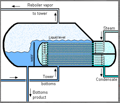
The kettle type exchanger also uses the same working method for shell and tube heat exchanger but the importance of this type is that, it is used for partially vaporizing the shell fluid. It is used as a kettle reboiler in process industry and flooded chillers in refrigeration industry.
The most distinguished feature of kettle type exchanger is its shape. It consists of a horizontal U tube or floating head bundle placed in a oversized shell. The tube bundle is free to move and removable. The large empty space above the tube bundle acts as a vapour disengaging space.
The liquid to be vaporized enters at the bottom, near the tube sheet, and covers the tube bundle; the vapour occupies the upper space in the shell, and the dry vapour exists from the top nozzles, while a weir helps to maintain the liquid level over the tube bundle. The bottom nozzle in this space is used to drain the excel liquid.
A figure and a working animation is provided here for kettle type exchanger.
2. Plate type heat exchangers
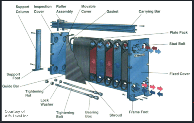
This type of exchangers is generally used for low pressure & low temperature application. These usually consist of end covers, carrying bars, inlet/outlet nozzles, plates and gaskets. See fig below
The carrying bar carries two end plates and a no of thin plates with gasket between them. These plates have flow patterns carved out on them on which the fluid flows. The plates are arranged alternatively so that hot fluid flows in 1, 3 and 5 numbered plate while cold fluid flows in 2, 4 & 6 numbered plates. This arrangement lets the hot and cold fluid exchange heat while not mixing.
The plate type heat exchanger requires less installation and maintenance space than shell and tube type of equivalent surface. An working animation is provide below for plate type heat exchanger.
3. Spiral heat exchangers
Spiral heat exchangers are generally used in chemical plants and are of circular construction. There are two plate strips wrapped to form a concentric spiral passage. They are arranged such that they form two concentric flow channel .The hot fluid flow in one channel and just next to it the cold fluid. This side by side flow is the basis for heat exchange between two fluids without mixing.
Similar to plate exchanger the spiral exchanger is compact and requires less installation and maintenance space.
Below is a working animation for spiral heat exchangers.
4. Double pipe heat exchangers
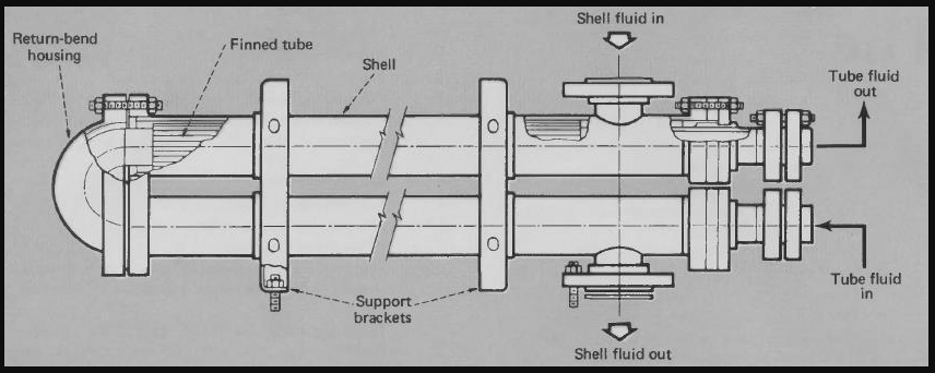
Double pipe heat exchangers are used when one liquid has a greater resistance to heat flow than another or when the surface area is small. In such cases the addition of fins to the inner pipe increases the surface area available for heat transfer and in terms increases efficiency of heat transfer.
Double pipe heat exchanger consists of an outer pipe and an inner pipe. Both outer and inner pipe have a return bend at one end. The inner pipe is fitted with fins while the outer pipe acts as a shell. Shell nozzles are mounted vertically from the outer pipe and the tube nozzles are directly welded to the inner pipe ends.
Below is a figure and working animation for Double pipe heat exchangers.
5. Air cooler heat exchangers
Air cooled heat exchanger perform their cooling function by flowing large quantity of cooled air around a bank of finned tubes by the help of large fans. The combination of FINned tube and the air circulating FAN has made FIN-FAN cooler a common term used for air coolers.
Air cooled heat exchanger will be discussed in a separate article.
Leave a Reply