In this article, we will point out some of the main considerations that we need to take care of while doing piping routing for a shell and tube heat exchanger. These considerations are given below.
Maintenance Access
The working spaces should be kept clear of any piping and accessories to facilitate channel, shell cover, and tube bundle removal, as well as maintenance and cleaning.
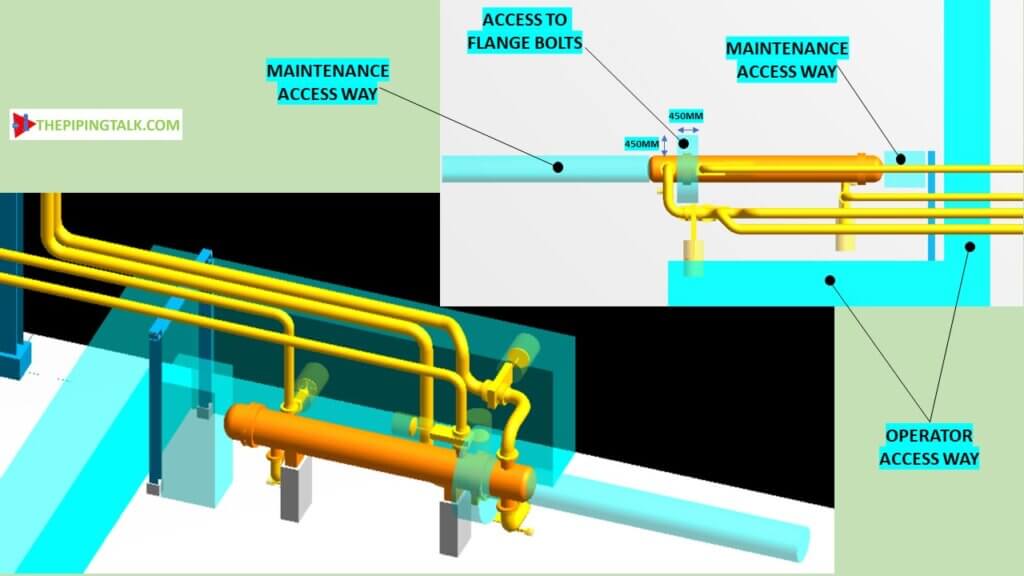
At the front, space required for tube bundle removal is = Tube length+(450 to 1500mm) * (this recommended length varies from 450mm to 1500mm. 1500mm is usually sufficient)
At the rear, a minimum of 1500 is required for cover removal.
For flange bolt removal 450 mm of clear space all around to be provided.
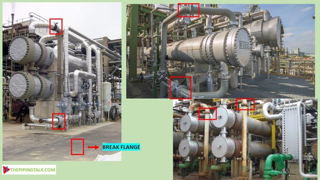
Break flanges requirement
During maintenance, the channel head of the heat exchanger has to be removed. For this purpose, the channel head nozzle has to be furnished with a breakout flange. Design the piping so that the channel end of the exchanger can be removed without removing the isolation valves.
Valve Location
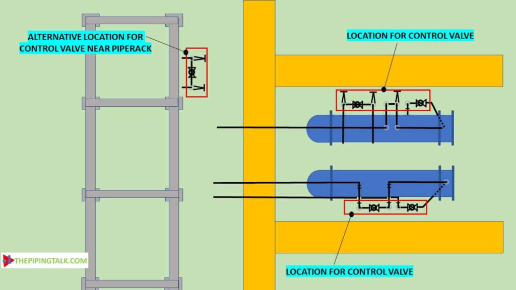
For valves and blinds, the best location is directly at the exchanger nozzle. In the case of an elbow nozzle on an exchanger, it should be checked that sufficient clearances are provided between the valve handwheel and outside of the exchanger.
Valve handles should be made accessible from the grade and from the access way. Free space at the side of horizontal shell neat access ways should be used for arranging manifolds, control valves stations, and instruments. Alternatively, the control valve stations can be arranged near the pipe rack.
Orifice location
Orifice should be placed in horizontal piping runs just above the headroom. The orifice should always be accessed from a mobile ladder.
Gauge location
Locally mounted pressure – and temperature indicators can be placed on exchanger piping or exchanger nozzles, on the shell or process lines, should be visible from the access aisle.
Heat Exchanger piping routing points
1A. If the line connecting to the heat exchanger is approaching it from the right side of the pipe rack or yard it should turn right from the heat exchanger center line and those lines which are approaching the heat exchanger from the left should turn left from its centerline. This is to avoid criss-cross routing near the exchanger.
1B. lines with valves should turn towards the access space with the valves/ control valve placed close to the exchanger.
1C. Utility lines (E.g., steam lines) connecting to a utility header on the pipe rack can be arranged on either side of the heat exchanger to minimize piping run.
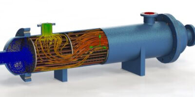
A User controllable 3d model is provided below for reference. It shows a basic heat exchanger piping arrangement.
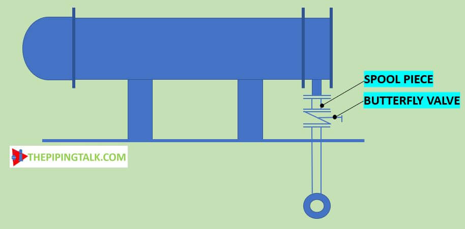
1D. If the cooling water line is underground then it should run directly under the lined-up channel head nozzle. So that the branch connecting the channel head nozzle to the cooling water header will be straight without any bend. provide a spool piece as shown below when a butterfly valve has to be used in this line.
1E. To avoid condensate drainage toward the exchanger, the preferred connection for steam lines is to the top of the header. However, there is nothing wrong with having a steam connection from the bottom of the header if steam traps are placed at the low point.
1F. Pipeline connecting the exchanger with adjacent process equipment can run point to point just above the required headroom.
1G. loops, pockets to be avoided. The designer should analyze the whole length of piping routed from the exchanger to some other equipment, aiming to provide no more than one high point and one low point, no matter how long the line.
1H. Piping should be elevated minimum distance (≈2200mm) from grade or platform overhead for operator headroom clearance. It also can be elevated to meet the designated pipe rack elevation. Where it can run at ground level, a clearance of a minimum of 300 mm from grade should be there.
1I. Clearance between the bottom of pipe and grade should be kept 150 to 200 mm considering the space required for the drain valve.
Heat exchanger piping Supports
2A. Excessive piping strains on the exchanger nozzles from the actual weight of pipe and fittings and forces of thermal expansion should be avoided by providing an adequate type of support at the proper location.
2B. The piping shall be arranged in such a way that no temporary support will be required for removing the channel and tube bundle.
2C. For stress analysis, while routing the pipe itself the fixed and free saddle position of the heat exchanger to be considered.
Heat exchanger bypass arrangement
Generally, bypass piping around exchangers is provided for temperature control and to allow cleaning during the operation of the rest of the process unit. There may be cases when the increase in operating efficiency resulting from cleaning or repair during the operation of the rest of the process unit would justify the cost of installing a bypass. Block valves need not be provided on the process side of the exchanger except where the valve is needed for flow control or where the exchanger may be bypassed while the unit is running.
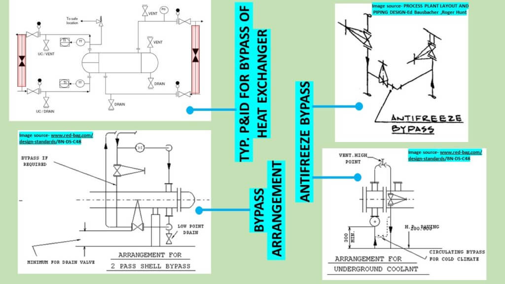
Provide a bypass line between the cooling water supply and return lines to prevent freezing when the exchanger is out of service.
References:
ED Bausbacher, Roger Hunt, 1993, process plant layout and piping design, PTR patience hall, inc
Red-bag design standard: bn-ds-c48
Leave a Reply