The relative position of exchangers with respect to other equipment in a petrochemical plant can be evaluated readily from the flow diagram. The following general classification can be followed.
1. Exchangers that must be next to other equipment.
Exchangers such as the reboilers, should be located next to their respective towers. According to process requirements there are condensers, which should be next to their reflux drums close to the tower.
2. Exchangers that should be close to other process equipment.
Some examples are exchangers in closed pump circuit, overhead condensers which should be close to their tower to ensure that the line pressure drop is minimal. Also where there is a tower bottom draw off –to heat exchanger-to pump flow, the exchangers should be close to the tower or drum for short suction line.
3. Exchangers that should be located between distant process equipment.
An example would be exchangers with process lines connected to both shell and tube side, which are far away from each other. Here exchangers can be placed where the two streams meets and the best location is on that side of the yard where the majority of related equipment is placed. Other locations cost more in pipe runs.
4. Exchangers that should be located near battery limit
If the Exchanger is between process equipment and the battery limit, like product coolers, it should be located near the battery limit to reduce pipe run.
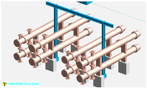
5. Exchangers that can be stacked.
A further step in the layout is to establish which exchangers can be stacked to simplify piping and save plot space. Most units in the same service are grouped automatically. Two exchangers in series or parallel usually are stacked. Sometimes, small diameter exchangers in series can be stacked three high. Two exchangers in dissimilar services also can be stacked. Sufficient clearance must be provided for shell and channel side piping between the two exchangers.
How to decide on elevation of Heat Exchanger/foundation height -:
1. Where process requirements dictate the elevation, it usually is noted on the P&lD. the minimum elevation requirements will be as shown on the mechanical flow diagram, deviation from the minimum elevation must be approved by the process engineer.
2. From the economic point of view grade is the best location of the equipment, where it also is more convenient for the tube bundle handling and general maintenance.
3. Exchanger will be elevated to satisfy the following
* Gravity flow of product from 1 piece of equipment to another.
* Required net positive suction head on a pump.
* Other mechanical or process requirements.
4. To elevate exchangers without specific requirements, the following procedure is recommended:
Select the exchanger which has the largest sized bottom connection. Take the dimension of this nozzle face to heat exchanger centreline. Add to it the connecting flange (height) dimension + the height of same sized LR elbow (1.5 X OD) + 300 mm for clearance above grade if drain point is valve or 230mm if drain point is plugged. This will get you the dimension of required dimension from grade to horizontal Centreline of exchanger.
From the above subtract the dimension of centreline of exchanger to underside of the base of exchanger as known from exchanger drawing, and you will get the finished height of foundation with grout. See Fig 2A for an illustration
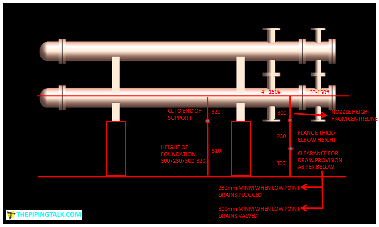
It is preferable if this foundation height can be made common for all the exchangers in the bank. If this is impracticable due to extremes of shell or connection pipe sizes, then perhaps two heights can be decided on.
General points to consider for equipment layout of heat exchanger in a chemical plant:
Access space around heat exchanger:
5. Leave space and access around the exchanger flanges and heads, and tube bundle cleaning/pulling space in front and in line with the shell.
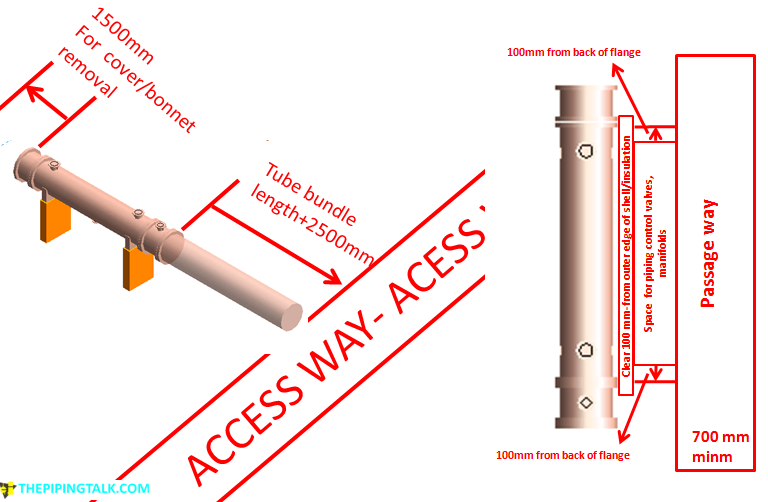
At the front or channel end minimum distance of the tube length plus 1500mm is considered sufficient. This bundle pulling space shall be shown on plot plan and it may extend over access ways within a unit area or over peripheral roads, which are not required to access other plants.
At rear end heat exchangers should have minimum 1500 mm clear space to remove cover.
Access space to be preserved on one side of heat exchanger can be arrived at through below process-
Decide the preferred side of heat exchanger on which piping controls is more suitable. on that side you should leave space
(a) Minimum 100mm from outer edge of exchanger shell
(b) Minimum distance to accommodated piping and control valves. This can be for e.g outer dia of flange + minm 100 mm
(c) Minimum 700mm for passage way. Refer fig-3A for the same.
On the side opposite to the piping and access way there may be another exchanger or any other plant equipment; in that case general plant equipment spacing rules are to be followed. So now we have covered all 4 sides of heat exchanger and the access space required for them.
6. If process requirement permits shell and tube exchangers can be placed vertically, supported by lugs and tower nozzles in a tower supported installation, steel structures and concrete piers. Investigate platform loading, if exchanger channel or head is to rest on platform during maintenance, provide for removal handrail where required for tube removal. Space should be provided adequately for vertical shell and tube heat exchanger for tube bundle removal.
Also Clearances for mobile crane boom for tube removal and access area at grade for mobile handling equipment must be checked and preserved.
Orientation of heat exchanger:
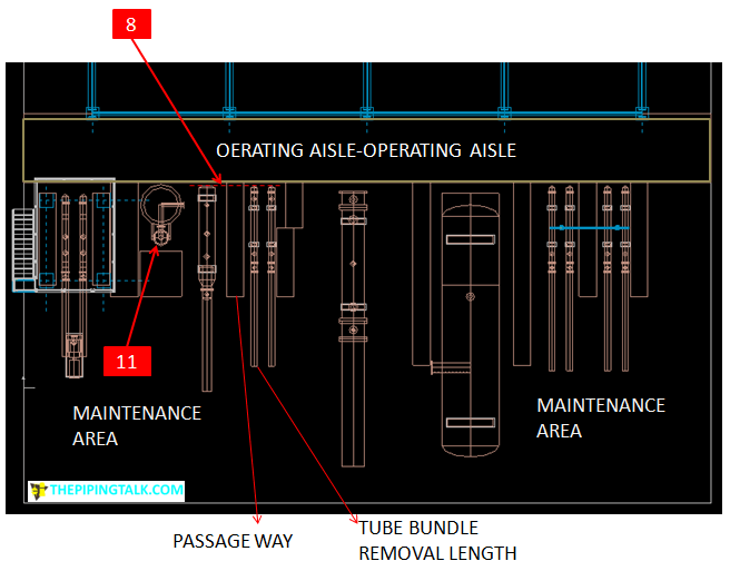
7. Horizontal shell and tube heat exchangers are placed so that channel end faces the auxiliary road or maintenance access way for tube bundle removal.
8. On layout line up all exchanger shell covers on operating aisle way for maintenance clearance except when underground cooling water lines are directly below channel end nozzles. When this condition exists, line up channel end nozzles and it should be directed towards access road or maintenance area.
9. While locating exchangers in a row, arrange the saddle to have more economical overall (lined up or combined) foundation / structure design. Further, travelling gantry can be provided in such c&e to handle a row of exchangers.
10. Groups of shell and tube heat exchangers shall be located such to align the channel nozzle in vertical plane in order to present a neat appearance and make pipe detailing easier.
11. Vertical reboilers will be arranged on back side of the vessel (side of vessel facing away from pipe way).allow space to break flanges and drop reboiler bottom head.
Distance between heat exchanger:
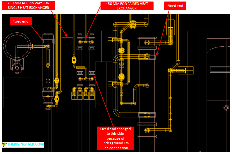
12. Exchangers can be located as single item or in pairs. When there is no intermediate control (i.e valves that need access in between exchangers) it can also be places in large groups. These paired and grouped heat exchangers can be operated in series or parallel.
13. Single heat exchangers when placed adjacent to each other a clear access way of 750 mm i.e clear space between the shells or associated pipe work and insulation is considered adequate. Whereas paired heat exchangers are placed with minimum 450 mm distance apart between the outside of adjacent channel or bonnet flange for maintenance purpose.
14. Exchangers can be stacked up to a height of 3600 mm from ground or platform. Stacking height more than this requires consideration for platform or fixed handling devices for access to channel and bonnet flanges.
Heat exchanger support:
15. Each shell&tube heat exchanger has two support feet, one with slots to permit thermal expansion and the other is considered anchor end. The end of the exchanger adjacent to the rack normally is the fixed end but if the CW headers are underground, the fixed end is changed to the channel end where cooling water pipes are connected. see Fig-5A. Anyhow other than the case of underground CW header as noted above, the result of piping flexibility should prevail over any other guidelines.
16. Horizontal reboiler anchor location depends upon relationship of vessel anchor one end only.
17. Thermo-syphon reboiler may be supported from the adjacent vessel or from independent structure from grade. In either case the method and location of the support will be determined by piping stress .location of support will be determined on the basis of minimizing differential movement between the reboiler piping and the vessel. When possible it is adviced to support the thermo-syphon reboilers independent of platform to improve maintenance and operation accessibility.
sara
Thanks, the information and figures are informative and helpful.In order to have a complete guide, I would suggest to add instructions on piping requirements around the heat exchangers as well.