The Basic working of a Gas turbine can be seen in the above video. Gas turbines come with different shaft arrangements to suit the application. According to this, the gas turbine can be categorized as a single shaft, two shafts, or multi-shaft engine.
Single shaft Gas turbine:
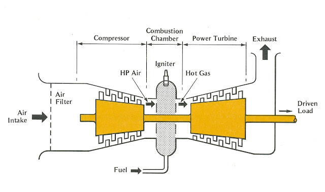
In Single shaft gas turbines, the turbine, compressor, and driven load are on a single common shaft. The hot gas from the combustor drives the turbine, the turbine, in turn, drives the compressor utilizing some of the energy, and the remaining energy is utilized to run the load (generator, compressor, pumps, etc.). In practice something like 80% of the power developed in the turbine from the combustion is needed to drive the compressor, leaving only about 20% ‘payload’ to drive the load. Because the compressor and turbine are running on the same shaft they run at the same speed. In a single-shaft gas turbine, the power turbine is usually coupled to the driven load (a generator or compressor) through a gearbox. The compressor and power turbine, therefore, run at a fixed speed, which is the generator speed multiplied by the gear ratio.
Two shaft Gas turbine: (also referred to as Split shaft gas turbine)
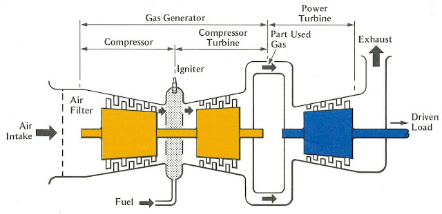
Two shaft gas turbines have two no’s of turbine. One is HP turbine (high pressure) and the other one is LP turbine (low pressure or power turbine). The hot gas from the combustor runs both the HP & LP turbine. The HP turbine only drives the compressor, as they are on the same shaft. The LP turbine runs on the second shaft, and it drives the load, usually at a speed different from that of the compressor/HP turbine. In a two-shaft turbine, the compressor and the power turbine can, and do, run at different speeds. The power turbine is coupled to the load and runs at governed speed, but the compressor speed varies with the loading. At light load, it will be idling, but as loading increases, it increases its speed up to the full load, when it will generally be running much faster than the power turbine. This feature greatly improves the fuel economy and extends the life of a gas turbine.
Multiple spool Gas turbine: (also referred to as twin-spool or multistage gas turbine)
below highlighted is an excerpt from the book “HIH Saravanamutto, H. Cohen, GFC Rogers, 2013, Gas Turbine Theory, Pearson”
High thermal efficiency for a gas turbine can be achieved by obtaining a high-pressure ratio. For compression, mostly an axial compressor is used in the gas turbine. At full power, the density of air at the rear end of the axial compressor is much higher than at the inlet. The compressor rotor blades and compressor dimensions at exist are designed according to this flow and density. However, when the compressor is operated at a speed below the design value, the air density at the rear is much too low (not as higher as designed). This results in excessive velocities and breakdown of flow which can cause violent aerodynamic vibration and reversal of the flow. This condition can exist during low power or during start-up, causing the gas turbine flameout or overheating. This is particularly severe when attempting to obtain a pressure ratio of 8:1 in a single compressor.
one way of overcoming this problem is to split the compressor into one or more sections. In this context we mean mechanical separation, permitting each section to run at different rotational speeds. The low-pressure compressor is driven by the low-pressure turbine and the high-pressure compressor by the high-pressure turbine. Power may be taken from either the low-pressure shaft or from a separate power turbine. The configuration shown below is usually referred to as a multi-shaft or twin-spool engine.
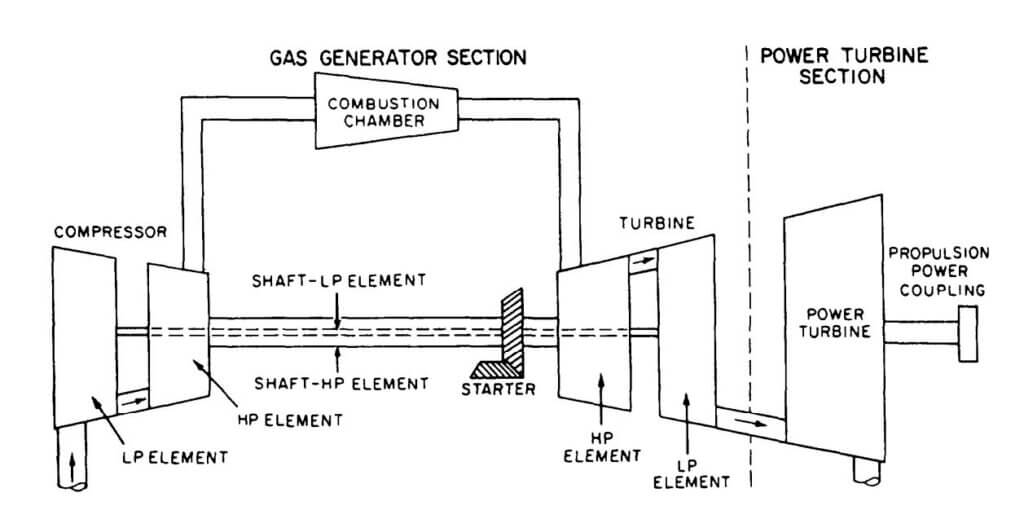
Summarizing the above, multi-shaft engines have more than two shafts. It has two compressor sections, the HP and LP compressor. There are also two turbines, the HP and LP turbine. LP compressor is driven by an LP turbine on a shaft that rotates concentrically within the shaft that is used for the HP turbine to drive the HP compressor. These two shafts run at different speeds. The energy left in the gas after this process is used to drive a power turbine (on a third, separate shaft), or the LP shaft is used as an output shaft.
The twin-spool layout was primarily developed for the aircraft engines, but there are many examples of shaft power derivatives of these. Current examples include the SGT A35 (Industrial RB211) and the GE LM 1600.
Starting motor in single shaft vs two shaft:
In single shaft engines, the starter motor has to rotate the gas compressor, turbine, reduction gear. But in the case of a two-shaft engine the power turbine, reduction gear is stationary until the gas generator reaches the approximate idle speed. So, the starting motor in the case of a two-shaft engine has to drive only the gas turbine, lowering the overall starting torque required as compared to a single shaft gas turbine.
Speed control in single shaft vs two shaft:
In single-shaft turbines, the governor controls speed by regulating the gas control valve or the liquid fuel valve. In two-shaft gas turbines, the governor itself is driven from the power turbine shaft but regulates the fuel input to the gas generator. This runs at such a speed as to provide just enough gas to the power turbine to keep it at its correct speed. Thus, as load increases, the gas generator speeds up, but the power turbine stays at a constant speed.
Single shaft vs two-shaft gas turbines- as driven equipment for electric generator:
In the case of electric generators, mostly the load speed remains constant. In such cases where a gas turbine has to drive a generator producing electricity, often a single shaft machine is specified because it can operate efficiently at a constant speed. The flexibility of operation, i.e., the rapidity with which the machine can accommodate itself to changes of load and rotational speed, is unimportant in this application.
In a cogeneration facility or a combined cycle power plant the single shaft gas turbine has a slight disadvantage over the two-shaft engine. This is because when the generator load is reduced, the constant airflow and compressor power in a single shaft unit result in a larger decrease in exhaust temperature. This in turn necessitates the burning of additional fuel in the waste heat boiler. Had it been a two-shaft gas turbine, burning the excess fuel would be unnecessary because it can maintain an optimum speed for the gas generator even with a reduced load.
The compressor of a single-shaft engine is constrained to turn at some multiple of the load speed, fixed by the transmission gear ratio so that a reduction in load speed implies a reduction in compressor speed. This results in a reduction in mass flow, hence of power and torque. But due to the reason specified in the previous paragraph, for a two-shaft engine even when the load decreases the compressor maintains a constant speed. For fixed gas generator operating conditions, a reduction in output speed results in an increase in torque for two shaft engines.
Two shaft engines when used to drive a generator, the free power turbine may be designed to run at the generator speed without a gearbox.
Single shaft vs two-shaft gas turbines- as driven equipment for mechanical drive:
In the case of mechanical drives such as compressors & pumps, the load is not always constant. It needs to be driven at varying speeds. In these cases where the flexibility of operation is important, often a two-shaft configuration is used. Two shaft configuration allows greater speed-horsepower flexibility than the single shaft system because the power turbine can run at an independent speed. In this type the power turbine could be designed to operate at the same speed as the driven equipment, potentially eliminating the need for a gear unit and its losses, which typically run 2–4%.
A single shaft turbine can’t supply the high torque required to start a large pump or compressor under full pressure. However, providing an electric motor with a variable speed drive (VSD) to help during start-up can enable the use of such a gas turbine in a train with a large pump or compressor. For a two-shaft gas turbine, as discussed earlier, the advantage is that the starter motor torque required will be comparatively less.
References:
“HIH Saravanamutto, H. Cohen, GFC Rogers, 2013, Gas Turbine Theory, Pearson”
https://www.turbomachinerymag.com/view/choosing-gas-turbines-single-vs-two-shaft
Muhammad Nadeem
Such a Very simple and good statement of GT related. No any confuses.
Easy to understand for everyone