A compressor is always a piece of driven equipment. This means we will need a driver which will efficiently supply torque of a specified value at a certain speed to rotate the compressor. The drivers are also called prime movers. But what types of drivers are currently used? We will discuss it in this article.
“Anything that is used to drive the compressor, the pump, the generator, is considered a prime mover. If a turbine turns a compressor, it is a prime mover. If a turbine turns the shaft of a generator, then the turbine is the prime mover. If a turbine turns a pump, it’s a prime mover for the pump” .
The selection of the driver for a compressor is finalized after thorough consideration given to the below points:-
- Operating parameter of the compressor
- Availability of power source. – if electricity is available an electric motor may be preferred and in plants where steam or gas is readily available then a steam turbine or gas turbine can be preferred.
- Auxiliary systems required for each driver.
- Results of mechanical analysis for the drive train.
- Maintainability and capital cost-Relative historical service lives of the prime mover categories before extensive and expensive unit overhauls are:
>slow-speed gas engine (300–600 rpm): 75,000 operating hours,
>high-speed gas engine (900–1800 rpm): 25,000–50,000 operating hours,
>gas turbine: 30,000 operating hours,
>electric motor: 100,000 hours,
Drivers for compressor:
Common drivers used to drive a compressor in the oil and gas industry is listed below.
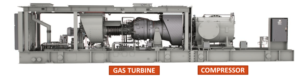
Gas Turbine
Gas turbines are well suited to drive the centrifugal compressor. A gas turbine is considered at places where there is an availability of gas fuel. Due to its lightweight compared to other types of drivers, it is used where minimizing weight is a priority (such as offshore). The gas turbines operate at a higher speed. Both industrial type or an aero-derivative type can be used to drive a compressor.
Gas turbines are built with different shaft arrangements. These can be categorized as a (1) single shaft gas turbine (2) Two shaft gas turbines (3) multiple spool engines.
The speed of a compressor is not always constant and it has to be driven with varying speeds according to process compression parameters. In a two-shaft gas turbine, the high-pressure turbine drives the gas compressor which is connected to it through a shaft. the low-pressure turbine also called a power turbine is on a second independent shaft. the speed of the power turbine in a two-shaft gas turbine can be controlled according to the speed requirement of the mechanical drive to which it is connected (in this case a process compressor). Because it can efficiently drive the compressor with varying speeds, two shaft gas engines are preferred to drive mechanical equipment such as a compressor. Nonetheless, multi-spool engines which also have this advantage are also used to drive compressors. Current examples include the SGT A35 (Industrial RB211) and the GE LM 1600.
To read more on the applications of single, two shaft, and multiple spool engines click here
Electric Motor Driver
In an electric motor, the current is applied to the stator to create a rotating magnetic field, the rotor which is an electromagnet reacts with the magnetic field to rotate within the stator.
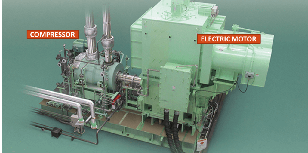
Electric motors are well suited for reciprocating compressors due to their similar operating speed. It is also used to drive centrifugal compressors. By its nature, it requires a consistent source of electric power. An induction motor, a synchronous motor, or a DC motor can be used. However, the induction motor is the most common among these.
Induction Motor
In an induction motor, the alternating (AC) current is supplied directly to the stator. This produces a rotating magnetic field (RMF) in the stator. This RMF will cause current to be induced in the rotor squirrel cage, this current in turn will create magnetic flux in the rotor. The magnetic flux created in the rotor will try to catch up with the RMF produced in the stator by rotating itself. Due to the lag between the flux current in the rotor and stator, the rotor will never reach the RMF speed (i.e., the synchronous speed). That’s why it’s also called an asynchronous motor. Below video explains the above in much detail.
For 3600-rpm compressor drives below 5000 hp, simplicity of installation almost dictates using the two-pole induction motor. No gear is required, and the overall electrical and mechanical installation is the simplest possible.
Synchronous Motors
Synchronous motors are electric motors whose rotational speed is in synchronization with the frequency of AC. Two major types of synchronous motors are (a) non-excited or permanent magnet design (b) direct current excited. The working of a synchronous motor is explained in great detail in the below-linked video.
Synchronous motors need excitation and are more complex and expansive than the induction motor. But still, it is preferred in some cases, because of its advantages over induction motor as listed below.
(a) Rotational speed is independent of the load. The motor operates at constant RPM (revolutions per minute). (b) Efficiency is higher than of an induction motor of the same output and voltage rating because there are neither losses related to slip nor the additional losses due to magnetizing current. (c) noise and vibration are generally less than with the induction motors. (d) Synchronous motors help improve overall power factor and may eliminate the need for power factor correction equipment, for example, capacitor banks.
Synchronous motors are an obvious choice to drive large, low-speed reciprocating compressors requiring motor speed below 600RPM. They are also useful on many large, high-speed drives. Typical applications include geared, high-speed (above 3600 RPM) centrifugal compressor drives for several thousand horsepowers.
Variable Frequency Drive (VFD)
When motors are supplied directly from a power network, the frequency (50Hz/60Hz, etc.) remains constant, whereas the voltage and current change according to the load. In other words, when the motor is connected directly to the power network, the speed of the motor is dictated by the network frequency, which is fixed and cannot be controlled.
Induction and synchronous motors are designed for a specific voltage per frequency ratio (V/Hz). This V/Hz ratio is more or less proportional to the torque developed by the motor shaft. When the ratio of V/Hz supplied to the motor is more there is a chance of overheating and this can lead to motor failure. Vice versa, when the V/Hz supplied to the motor is less, this affects the capability of the motor to handle the load.
Variable frequency drives work by varying the frequency supplied to the motor, which in turn adjust the speed (RPM) of the motor. Along with varying the speed of the motor, VFDS can also Ramp up the motor speed during startup and prevent the heavy load to strain the motor during startup. The VFDs can work with PLC (PROGRAMMABLE LOGIC CONTROLLER). PLC can monitor process conditions and accordingly control the speed of the motor through a VFD.
The thing to consider for a VFD is its large cabinet size, which houses the electronics. If located in an air conditioning space, the air conditioning must be sized to accommodate the additional heat load due to it, which is significant for larger drives.
For centrifugal compressor, an induction or a synchronous motor or a VFD can be used to drive a centrifugal compressor. The reciprocating compressor produces an oscillating load. While the gas is compressed and discharged in the forward stroke, in the backward stroke it is expanded, this makes the torque increase and decrease with each revolution. For this often the driver motors are sized with the average torque. But severe torque pulsation can exceed the mean torque. This torque pulsation is partially absorbed by the inertia of the flywheel (when present) or the inertia of the motor.
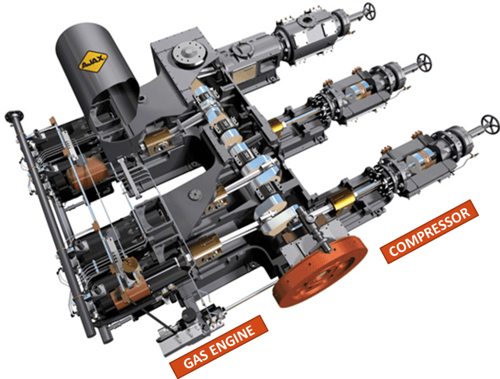
Gas Engine
Levels of complexity for gas engines are in-between that of a gas turbine and an electric motor. They are normally used in applications where the use of a gas turbine or an electric motor is more complex or costly to execute.
The gas engine most commonly used in compressor applications is a reciprocating spark-ignited internal combustion engine fueled by natural gas itself. Reciprocating gas engines in their basic level can be divided into two types- two-strokes and four-strokes.
For engine starting, a small motor spins the engine up to a speed where combustion is consistent enough to sustain the rotation by itself, at which point the starter motor is disengaged. The compressor which is directly coupled to the engine places an additional load on the starter during starting.
The well-known integral-engine compressors used in the gas compression industry use the Gas engine as a driver. Here the reciprocating gas engines and a compressor are merged into an integral unit.
Gas Engine driven centrifugal compressors are very few. This combination is used only in low ratio applications and in fuel cost situations where the high engine efficiency is attractive. The difference in rotating speeds (engine 300 to 600 rpm, compressor 3000 to 5000 rpm +) requires the use of a speed increaser.
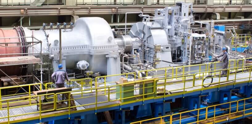
Steam Turbine
The steam turbine is a prime mover in which the potential energy of steam is converted into kinetic energy and the latter in turn is transformed into the mechanical energy of rotation of the turbine shaft. The turbine shaft, directly or with the help of reduction gearing, is connected with the driven mechanism which can be a generator or a compressor.
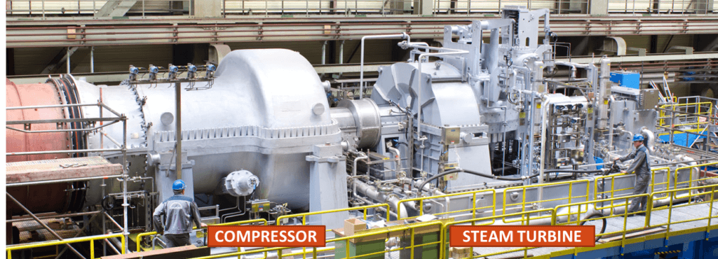
Steam turbines have a wide operating speed range which lends themselves to being ideal drivers for many styles of gas compressors including both dynamic (radial centrifugal and axial centrifugal) and positive displacement (rotary and reciprocating).
The variable speed “Mechanical drive” or “industrial drive” designations are often used to describe the type of steam turbine best suited for driving compressors. Mechanical drive steam turbines are typically multistage units and can be either straight-through flow or extraction/induction designs. They typically use a range of steam conditions up to 14MPa and 813 K and ranging in power to 69MW with speeds up to 14,000 rpm. This class of steam turbine can be directly coupled to the compressor or coupled through a speed-increasing gear to meet compressor speed requirements. Variable speed requirements make this turbine design well suited to compressor drive use as a wide variety of speed ranges can be supplied.
The back-pressure turbine is selected when process steam demands are greater than the steam required for process drivers such as large compressors. This type of turbine is also selected when various steam levels are required by the process. The back-pressure turbine is the most frequently selected among other types of steam turbines, as it has a lower capital cost, simple construction, is the most suitable turbine for high speeds, and is generally more reliable.
The condensing turbine is selected when steam demand for process drivers is greater than the low-pressure process steam requirements. It is also selected when no high-pressure steam is available. The advantages of condensing turbines are that it requires less change in the live steam for various turbine loads and is, therefore, easier to control. It also requires less steam. The disadvantages of condensing turbines are that it has a high capital cost because it is larger than a back-pressure type. It requires high specific volumes of steam, and there is the additional cost for a condenser and other auxiliary equipment. The condensing turbine has lower overall reliability & higher operating cost because the condenser, ejectors, extraction pumps, and other auxiliary equipment add to the complexity of the operation.
The induction-type turbine is selected when excess steam is available at an intermediate pressure. The extraction turbine is selected when there is a demand for intermediate-pressure steam and, in particular, when there is a variation in the amount of steam required. Both extraction and induction turbines provide some significant advantages and disadvantages listed below-
Advantages-
1. Process steam can be supplied at two or more pressures without having to purchase boilers operating at different pressures or having to throttle steam, which is a waste of useful energy.
2. Process steam requirements can be controlled at suitable pressure and volume required by the process and maintained at these conditions by extraction or induction turbines.
3. It is easier to make a plant steam balance using extraction or induction turbines.
Disadvantages-
1. Turbine blades can be excited by steam flowing through the intermediate nozzle, which can cause premature blade failure.
2. To control the intermediate pressures, extra valves are required.
3. Extra nozzles require a longer turbine shaft, which increases the span between bearings. This can produce significant vibration problems at critical speeds.
4. Extraction and induction turbines are about 5 % less efficient than back-pressure turbines.
Turboexpander
Turboexpanders provide the most efficient solution when it is required to reduce the pressure of a fluid stream. It converts gas or vapor energy into mechanical work as the gas or vapor expands through the turbine. There are two main types of expansion turbines: axial-flow and radial-flow.
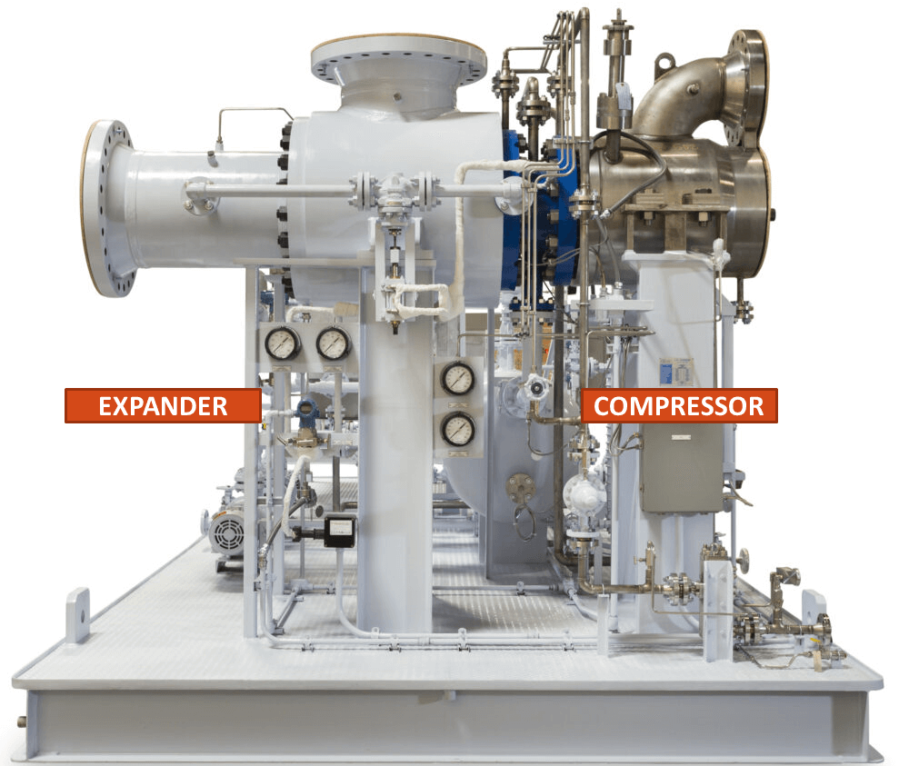
Expanders are generally custom-sized and can, therefore, be readily matched to the centrifugal or axial compressor. It also will match the screw compressor of the dry type, at least in the larger frames. A variation of the application of expanders to a compressor train is to include an induction motor-generator. The motor-generator acts as a starter to bring the compressor train to speed and permits the process to start. As the expander begins to recover energy, it first takes load from the compressor and, when excess torque becomes available, the induction machine acts as a generator.
Leave a Reply