Centrifugal compressor can be made into different configuration to suit specific services. the foremost being either a single stage centrifugal compressor or a multistage centrifugal compressor.
Single Stage compressor–
A single stage centrifugal compressor consists of a single impeller with associated guide vanes and diffuser. The compression ratio capability of the compressor is primarily a function of the impeller peripheral speed and blade geometry. Generally a single stage compressor can achieve up to a 3 to 1 compression ratio. The Flow capacities of these types range from 1000 cfm to 300,000 cfm. Initial cost for medium to high capacity range of single stage compressors is attractive than other types.
Single-stage centrifugal compressors may be configured as a beam design or with an overhung impeller arrangement. Various types are as following
Overhang single stage compressors
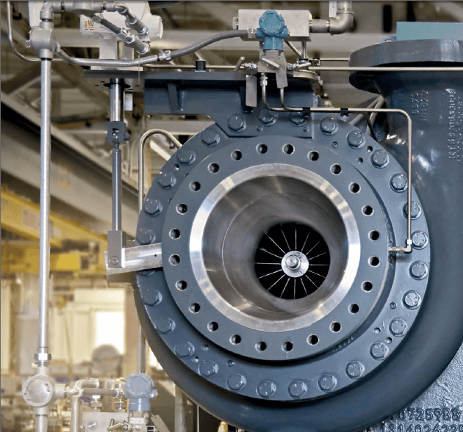
In the overhung configuration, the impeller is located at the non-drive end of the shaft (outboard of the non-drive end radial bearing). These type of compressors have axial flow suction nozzle, which give higher efficiency and a wide operating range. These are mainly designed for low pressure, high volume application. The compressor flow is controlled by inlet guide vane, suction/discharge throttle valve or by passing. Removal of impeller is not needed to do the maintenance of bearing; it can be done simply by opening the bearing casing. It can handle Gas flows up to 60,000 m³/hr and pressure ratio up to 3.5 can be achieved.
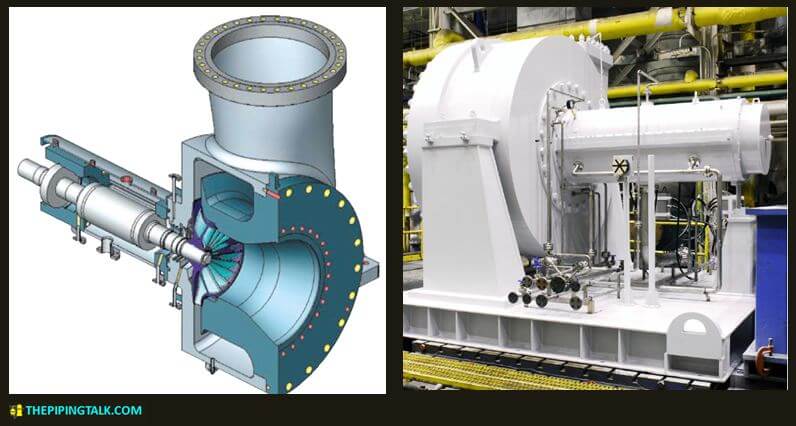
overhang single stage compressors are used mainly on coke gas service.
Between bearing design single stage compressors
In the between bearing configuration, the impeller is mounted between the bearings. The impellers are semi open type. It can handle Gas flows up to 40,000 m³/hr, pressure ratio up to 1.45 and discharge pressure up to 2 bar can be achieved.
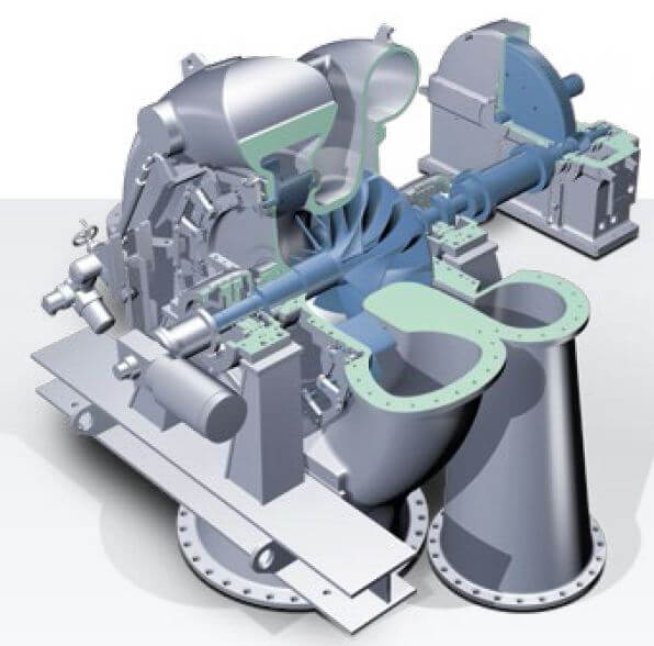
Between bearing design single stage compressors are mainly used as a booster or recycle compressor In petrochemical industries such as Ethylene oxide/Ethylene Glycol plant, propylene plant, polyethylene plant, chlorine , sulphuric acid plant , MVR (mechanical vapour recompressor) plant.
Integrally geared single stage compressors
Integrally geared single stage turbo compressors have overhung semi open impellers. Impeller is overhung mounted directly onto the high-speed shaft of gearbox. It can handle Gas flows up to 300,000 m³/hr, pressure ratio up to 3.5 and discharge pressure up to 50 bar can be achieved.
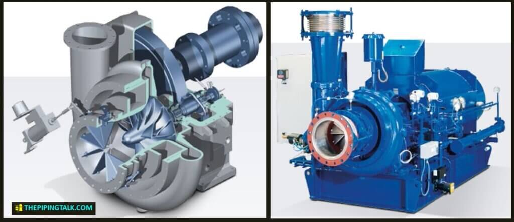
Integrally geared single stage compressors are used to serve demanding duties in clean process gas or air service.
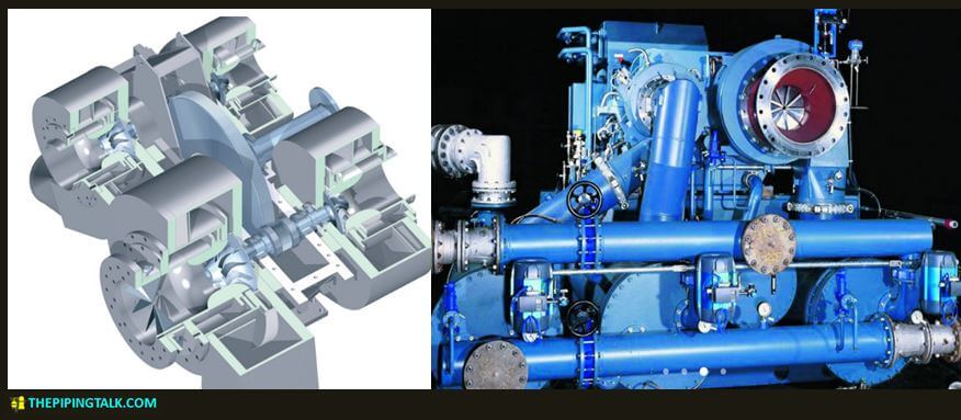
Multi Stage compressor –
When a single stage compressor with one impeller cannot meet the pressure requirements a multi stage centrifugal compressor is used. Multistage compressors consists of several impellers arranged one after another on rotor such that the discharge from the 1st impeller diffuser will enter a return passage way which guides it into the eye of the next impeller. So effectively pressure rises in 1st impeller and then again on the 2nd impeller and so on.
Multistage compressors can be divided into below categories with regards to their configurations needed to suit specific services and pressure rating-
1. Horizontally split casing compressors
2. Vertically split casing compressors
3. Compressors with bell casing
4. Pipeline compressor
5. Integrally geared compressors
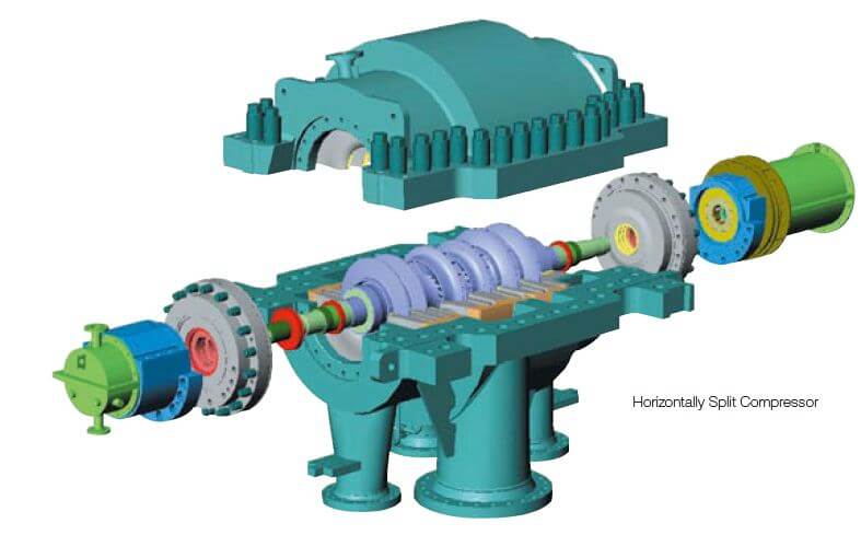
Horizontally split casing compressor –
In a horizontally split casing type compressor, the cylindrical casing is divided into two halves i.e the upper half and the lower half. These two are joined along the centreline by bolting. Because of the bolting and sealing limitation at the split it cannot sustain high pressure, thus it is used where the gas operating pressure is less than 60 bars (870 psi). In these types the advantage is maintenance of internal items can be done by only removing the upper half. For this most of the piping connection except main process in/out connection is given in lower half. The main process in/out connection is preferred in lower half but it may present in upper half also.
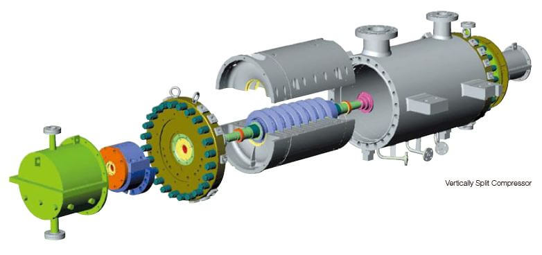
Vertically split casing compressors-
Vertically split casings are formed by a cylinder closed by two end covers, also referred as barrel. The advantage of the vertically split joint is its high-pressure capability due to the one-piece construction and conventional, proven flange type seals at each end. These machines which are generally multistage are used for high pressure services up to 680 bar (9900 psi).
Compressor with bell casing-
This is a type of vertical split or barrel compressors. Used for high pressures, these have bell shaped casings and are closed with shear rings instead of bolts.
Before we go into other categories it should be known that both horizontal and vertical split compressors can also be classified according to the compression stages they employ. So what is a compression stage?
A compression stage is a term that refers to the area of compression between two consecutive nozzles. Imagine in a compressor the process air enters through inlet nozzle gets compressed and it is discharged through the discharge nozzle, so here there is only 1 compression stage. But if in a compressor there is a provision for inter cooler connection then the compressor will have 4 nozzles. Air flow will enter through 1st inlet nozzle then it will get compressed and discharged through 1st discharge nozzle. This discharge then goes to intercooler gets cooled and again enters the same compressor through 2nd inlet nozzle get compressed and discharge through 2nd discharge nozzle. In this case we can say the compressor employs 2 compression stages.
Now according to compression stages employed, both horizontally split & vertical split centrifugal compressor can be divided as below
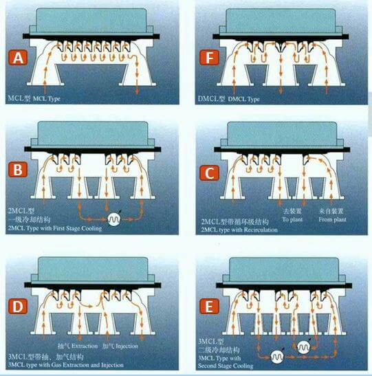
(A)- Multistage compressor with one compression stage. See Fig-7A.
(B)- Multistage compressor with two compression stage. The two compression stages are arranged in series within the compressor. Between the two stages the flow is passed through a inter cooler to cool off and increase the efficiency of compression or circulated back from the plant. See Fig-7B&7C. As said these are used when intermediate cooling is required or when a process calls for two separate compression stages.
(C)- Multistage compressor with more than two compression stages in a single casing. These are used when different gasses have to be compressed to different pressure levels by injecting or extracting gasses during compression. See Fig-7D&E. Additional side stream nozzles can be provided with these for special requirements such as in refrigeration applications, particularly for propane in LNG plants.
(D)- Multistage compressor with two compression stages arranged in parallel. Both the stages are identical and the flow enters from both the side gets compressed and discharged through a common discharge nozzle positioned at middle of the casing. See Fig-7F. These are also identified as Double flow models and used to compress very high flows. This solution allows the casing size and speed to remain within an acceptable range to couple the compressor to drivers and/or other compressor casings.
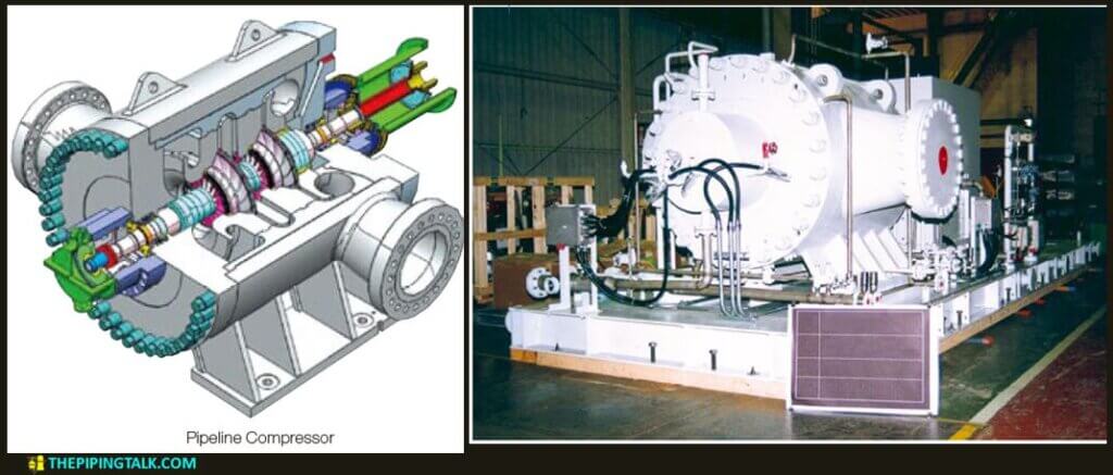
Pipeline compressor-
These have bell-shaped casings with a single vertical end cover. They are generally used for natural gas transportation. They normally have side suction and delivery nozzles positioned opposite each other to facilitate installation on gas pipelines. Axial inlet is also available when the pressure ratio allows for a single impeller. These are generally designed for pressure up to 100 bar (1400psi).
Integrally geared multistage compressors-
These are used either for low-flow/high pressure, or high-flow/low pressure conditions. This type of compressor has a bull gear and from one to four high speed pinions. One or two impellers can be mounted on each pinion-shaft. Optimal impeller speed and the ability to inter-cool compression stages guarantee very high efficiency. Due to its rugged mechanical design, this type of machine has very high reliability and is easy to maintain. A large variety of gases can be handled by this compressor line with appropriate construction materials and seal systems. These are designed for process air and gas service.
A working animation of integrally geared compressor is provided below.
References:
Maurice stewart, 2019, Surface production operations-Volume IV-pumps and compressor,Gulf professional publishing
Paul C. Hanlon, 2001, Compressor Handbook, McGraw-Hill,USA
Leave a Reply