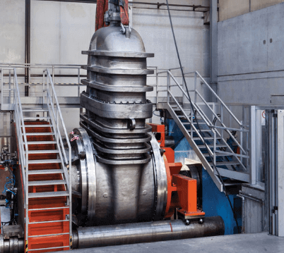
What is a Gate Valve?
Gate valve is an isolation valve .Gate valves open when a gate is lifted from the path of flow and close when the gate returns to its position (hence the name). Gate valves provide straight through unobstructed passage way, which results in minimum pressure loss. This unobstructed bore of gate valve also allows a passage for pig during pipe cleaning procedure.
Gate valves are cheaper than ball valves of same size and quality. They are generally slower in actuation than quarter-turn valves and are most commonly used in applications where valve operation is infrequent such as isolating valves. Because gate valves open slowly they also prevent water hammer effect. Gate valves are designed for fully open and fully closed services; these are not used for flow regulation purposes. In the fully closed position, gate valves provide a positive seal under pressure. However under very low pressure i.e 5 psi light seepage would not be considered abnormal with this kind of valve.
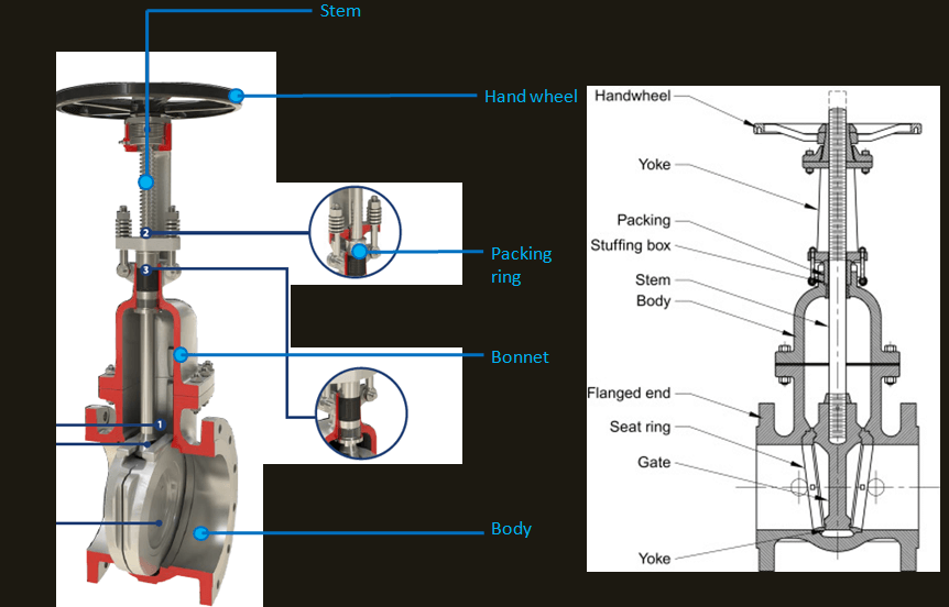
Parts of Gate valve:
Below is an image showing parts of a gate valve.
Classification of Gate Valves:
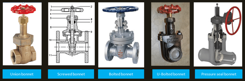
According to bonnet construction:
Bonnets for gate valve come in different designs to satisfy various requirements. The variants can be seen in below image.
The variant Pressure seal bonnet is described below
Pressure seal bonnet:
The main feature about the pressure seal
bonnet is that the body-bonnet joints seals improve as the internal pressure in
the valve increases, compared to other constructions where the increase in
internal pressure tends to create leaks in the body bonnet joint.
The basic operation of this kind of valve, where the seal is achieved from the
pressure exerted by the fluid flowing through the valve, is as follows:
Internal pressure forces the bonnet upwards against the gasket, creating forces
in the contact areas between the gasket and the bonnet and between the gasket
and the body.
Leaks most commonly arise at the contact surface between the gasket and the
body. The area where the body is in contact with the joint is covered by
stainless steel, improving surface’s quality and avoiding corrosion issues.
Gaskets are carefully designed to produce a tight seal regardless of the line
conditions that can be easily dismantled for maintenance operations.
Below is a animation of pressure seal bonnet gate valve:
According to Stem Construction:
there are three types of stem features which can be found in gate valve construction:
(1) Rising stem/outside screw and yoke,
(2) Rising stem/inside screw,
(3) Non rising stem/inside screw.
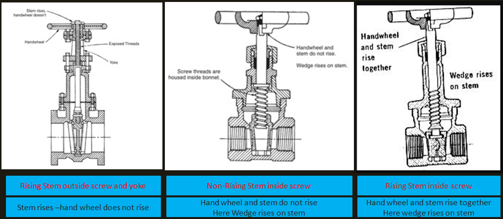
Rising Stem/Outside Screw and Yoke:
Rising stem/outside screw and yoke construction retains stem threads outside the valve. Rising stem/outside screw and yoke construction is recommended where high temperatures, corrosives, and solids in the line might damage stem threads inside the valve. When the hand wheel is turned, the stem rises as the yoke bushing engages the stem threads. The external threads enable easy lubrication; however, care must be taken to protect the exposed stem threads from damage. And advantage of rising stem valves is the ability to determine valve position by observing the position of the stem.
Rising Stem/Inside Screw:
Here the hand wheel and stem both rise, adequate clearance must be provided for
operation. The stem and hand wheel positions indicate the position of the disc
inside the valve. In the open position, the backseat helps protect the stem
threads; but, care must be taken to protect the stem externally.
Non rising Stem/Inside Screw:
Non rising stem/inside screw design has the chief advantage of requiring minimum headroom for operation. Since the stem does not travel vertically, packing wear is reduced. Heat, corrosion, erosion, and solids may damage the stem threads inside the valve and cause excessive wear. In addition, it is impossible to determine the disc position since the hand wheel and stem do not rise
According to wedge construction:
Gate valves are available with different disks or wedges. Four main types of discs are available in gate valves:
1. Solid-wedge disc
2. Double disc-parallel faced
3. Split-wedge disc,
4. Flexible-wedge disc.
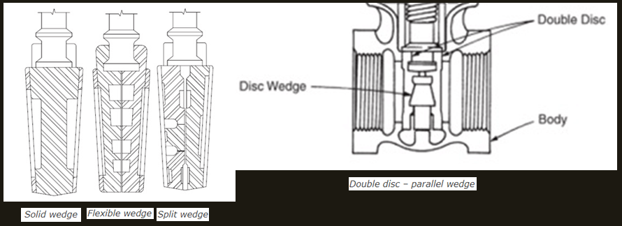
While parallel disks are used in valves having parallel seats, other three: solid, flexible and split wedges are used in valves having inclined seats.
Some of the above as well as some popular variants are discussed below.
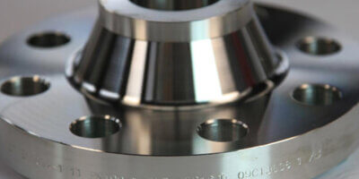
Wedge Gate Valve:
* The wedge shaped disc is utilised to introduce a high supplementary seating load that enables metal-seated wedge gate valves to seal not only against high, but also low, fluid pressures
* Wedge shaped solid and flexible gates are available.
* One piece solid wedge is used as they are easily made.
* Flexible wedges have a grove cut in it, which makes it sit on the seat surface more easily.
* Standard steel wedge gate valves should normally be specified with outside screw and yoke, rising stem, non rising hand wheel and bolted bonnet.
* Wedge gate valve does not shut off against high pressure gas as efficiently as slab or expanding gate valve so in those cases the later is specified.
* Gate vales ≤ 2” are provided with reduced port (sometimes called conventional or standard)
Parallel Expanding Gate Valves:
* These valves have inclined internal surface and parallel seats.
* The two gate halves are forced out against the seats at point of closure providing a tight sealing without the assistant of fluid pressure.
* Heavier in comparison with wedge or slab type. These are normally though conduit type but may also be available without a conduit.
* Expanding gate valves are not recommended for sandy / abrasive service. One reason for that is, the expanding action can tend to trap hard particles between gate and seat.
* Expanding gate valves should not be use in steam service.
Slab Gate Valves:
* These have a single parallel faced slab gate, which sides over floating seats. Sealing is by differential pressure.
* The gate design is always of the through conduit type.
* The basic design is suitable for use in a wide range of application eg well head isolation, process piping, tank etc.
* When ordering we have to make it clear to vendor regarding downstream sealing only or upstream + downstream sealing.
Parallel Slide Gate Valves:
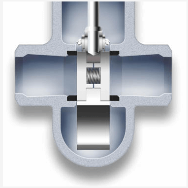
* These are made with 2 body pieces assembled with a spring in it.
* Valves like wedge type when closed in heat lines during hot temperature may be very difficult to open in cold temperature due to expansion. In those situation these valve are used instead.
*System pressure is used to provide isolation. The closing is only made over one of the seats. Higher the pressure in the system-better is the closing tightness.
*This design of gate valve is commonly used for clean fluids and steam applications.
Knife Gate Valves:
* Should not be used in hazardous service or high pressure service.
* This valve has a bevel on knife edged single piece parallel slide gate valve and is designed to handle slurry, solids which are liable to obstruct a wedge gate. The knife edge pushes aside and cuts through solids in the flow.
What Code and Standard are followed for gate valve?
Standard- API 600 (FOR SIZE 2” to 24”)
ASME B16.34 (IN GENERAL FOR LARGE SIZE)
API 602 (FOR SIZE 1/2” to 1-1/2”)
Gate valves are tested according to – API 598 Standard
siline
hi
I want to know on which principle to choose a valve to have a gate valve or another