
Introduction to Gas Turbine Combustion
Gas turbines turn fuel into energy. Some create shaft power for electricity, while others produce fast-moving air to push aircraft forward.
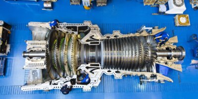
In a power generating Gas turbine, [1] Air from the environment enters through the inlet and passes through a multistage compressor [2] where its pressure is increased. The high pressure and hot air then enter the combustion chamber [3] where the fuel is added and burned, producing hot gases in the range of 927°C (1700°F) to 1593°C (2900°F). The hot combustion gases then enter a multistage turbine [4] where the energy of the hot gases is converted into mechanical energy.

Combustion is one of the key processes in gas turbines, and there are a few types of combustion systems that are predominantly used.
- Non-DLE (Non-Dry low emission system/Diffusion combustion)
- WLE-Wet low emissions
- DLE-Dry low emission system
Non-DLE system (Diffusion combustion)
In early gas turbines manufactured before 1990, the major goal was to produce higher combustion efficiency and burn different grades of fuel alike. In these legacy gas turbines, generally diffusion combustors were used, making them primarily non-DLE systems. At that time, there was no concept of the environmental impact of this.
The air enters the combustors in either a straight flow or reverse flow. Straight flow design is common in aero derivative gas turbine engines where whereas reverse flow is commonly used in large frame type unit.

Like most of the other combustors, the diffusion combustors have a recirculating zone, a primary burning zone, and a dilution zone.

The diffusion combustors use very little about 10% of the total air from the compressor for combustion due to the high BTU content of the gas, which requires much less oxygen to release the heat. The rest of the air is used for cooling and mixing.
Diffusion combustors have a single nozzle. In a diffusion combustor, the fuel is injected via a nozzle that sprays directly into the air stream inside the chamber, forming a diffusion flame in the recirculating zone. Due to this, in Non-DLE combustion systems the the primary zone flame temperature is typically very high, often in the range of ~1900 °C to 2100 °C (≈ 3450–3810 °F).
The swirling air formed in the recirculating zone stabilizes the flame. The heat of the recirculating zone also evaporates the liquid droplets to vapors in liquid fuel systems, so that it is easier to burn the vapors than the droplets. The partly burned fuels rich gases mix with the secondary air downstream the chamber, and because the fuel is already vaporized, warm, it burns extremely quickly once more oxygen is available. The function of the dilution zone is to mix the hot gases with the dilution air.
Problems with Non-DLE System
In a non-DLE or diffusion combustor, where the combustion temperature is high above 1800°C (3272°F), atmospheric nitrogen (N2) reacts with oxygen (02) to form nitric oxide (NO).
N2+O2→2NO
Nitric oxide (NO) formed above in the combustion can react with more oxygen (02) available in the exhaust or the atmosphere to form Nitrogen Dioxide (NO₂).
2NO+O2→2NO2
The NO and NO2 are the oxides of nitrogen and are collectively called NOx. These Nox are responsible for creating ground-level ozone, acid rain, impairing oxygen transport in blood at high levels, and creating many harmful particulate matter that damages lungs and causes respiratory issues.
Emissions from turbines are a function of temperature and thus a function of the fuel-to-air (F/A) ratio. The following graph shows that as the temperature increases, the amount of NOx emissions increases, whereas the amount of CO and the unburnt hydrocarbons decreases.

Environment protection agency rules for gas turbine emissions
In 1977, the Environmental Protection Agency (EPA) in the United States issued proposed rules that limited the emissions of new, modified, and reconstructed gas turbines to 75 volumetric parts per million (vppm) NOx at 15% oxygen (dry basis). Over the years, NOx limits have become stricter, dropping from 75 vppm to 25 vppm, and the latest gas turbine targets are as low as 2 vppm.
Systems available for removing NOX and CO
Normal combustion temperatures in gas turbines are around 3400–3500 °F (1871–1927 °C). At this level, the exhaust gases contain about 0.01% nitric oxide (NO). Lowering the combustion temperature helps reduce NO formation. If the burner temperature is kept below 2800 °F (1538 °C), the nitric oxide level can be controlled to less than 20 ppm (0.002%), which meets emission limits. Thus lowering the combustion temperature is one of the key factors. There are 2 major methods available for minimizing emissions by reducing combustion temperature.
- Wet low emissions (Water or steam injection into the combustor)
- Dry low emissions
Below is a brief about wet low emissions and Dry low emissions.
Wet low emissions (WLE)
It was found that NOx formation can be more than halved by reducing the flame temperature from 1600 °C to 1500 °C. One way of reducing flame temperature is to inject water or steam into the combustion chamber. This combustion process is called wet low emissions.

There are primarily three methods by which water is injected into a combustor-
1. Through the fuel nozzle: Demineralized water is mixed with fuel and injected directly into the combustor via the fuel nozzles. Fuel nozzles have extra passages to inject water into the combustor head end, where it mixes with the incoming air and reaches the hottest part of the flame for maximum cooling.
2. Separate Water Injection Ports: Dedicated injectors or ports introduce water independently into the combustion chamber, Upstream or near the swirler/fuel nozzle region.
For NOx control, a typical water spray nozzle directs the water injection spray toward the fuel nozzle tip swirler has been effective in controlling the NOx emissions.
3. Direct Injection into Combustion Zone: Water is sprayed directly into the flame region using high-pressure atomizers.
Steam injection for NOₓ reduction is done in the same way as water, entering through the combustor head end. However, steam is less effective because water’s high latent heat absorbs more heat from the flame, lowering its temperature more. Steam injection can be an option in a heat recovery steam generator in a combined cycle or cogeneration installation where steam is available at high pressure. The main drawback of the wet low emissions method is that it needs a lot of demineralized water—about half the amount of fuel to cut NOx by 40%. To achieve even lower NOx levels, the water-to-fuel ratio may need to be 1:1. In many places, water is scarce, and in countries with freezing weather, it’s not available year-round. Also, increasing the water-to-fuel ratio further can reduce NOx, but will cause higher CO and unburned hydrocarbon (UHC) emissions.
Dry low-emission DLE
We all have heard the term DLN (dry low NOx); DLN was the First acronym to be coined, but with the requirement to control NOx without increasing carbon monoxide and unburned hydrocarbons, this has now become DLEs (dry low emissions)
In DLE (Dry Low Emission) combustors, the fuel and air are mixed before entering the combustion chamber. This process is called premixing. In the DLE combustor, it is targeted to burn at least 75% of the fuel in a lean condition to avoid significant production of NOx.

To understand where premixing happens, let us take the example of a Siemens Energy DLE combustion system. While designs vary by manufacturer, Siemens Energy uses a radial swirler. Most of the fuel–air mixing takes place inside the swirler slots, where fuel is injected and blended with air before entering the primary combustion zone. The swirling motion of air further improves mixing and helps keep the flame stable.

Proceeding further, the DLE fuel injector is larger because it includes a premixing chamber and mixes a large amount of air—about 50–60% of the total combustion air. In lean combustion, the flame temperature is low, which can cause flameout at low engine loads. To prevent this, a small portion of the fuel is burned richer to create a stable “pilot” flame, while the rest is burned lean.
To maintain lean combustion down to about 50% engine load, one method is to gradually close the compressor inlet guide vanes as load decreases. This reduces engine airflow and keeps the fuel-air mixture in the combustion chamber more stable, especially in single-shaft machines.
Another method is to dump some air overboard either before or from the combustion section. This lowers airflow and increases the fuel flow needed for a given load, helping keep the fuel-to-air ratio nearly constant.
In a combustor without variable geometry (i.e., the airflow paths and mixing do not change with engine power), you cannot simply supply full fuel all at once. As the engine power increases, fuel must be added gradually in stages. This ensures the flame stays stable and avoids flameout or incomplete combustion. Gradual fueling allows the combustor to maintain the correct fuel-to-air ratio at each power level, since the airflow pattern cannot adjust itself. Typically, at least two or three stages are used.
There are two types of staged combustors:
Fuel-staged: Fuel is added in stages to control flame temperature and reduce NOx.
Air-staged: Air is added in stages to control flame temperature and emissions without changing fuel.

DLN/DLE combustors have many more fuel nozzles in each can-annular combustor can or annular combustor than a diffusion-type combustor, so that a lean mixture of fuel can be injected. A simple two-stage premixed combustor, as shown in figure below.

Below is a DLE combustion system that operates in four staged modes:
- Primary operation (ignition to 20% load): Fuel flows only to primary nozzles; flame is limited to the primary stage to start and run the engine at low to mid loads.
- Lean–lean operation (20–50% load): Fuel flows to both primary and secondary nozzles; flames in both stages handle intermediate loads.
- Secondary-stage transient (transfer to full load): Fuel flows only to secondary nozzles; flame shifts to the secondary zone while the primary zone is extinguished.
- Preload/full load (50–100% load): Fuel flows to both nozzles; flame remains in the secondary stage, achieving premix operation with optimum emissions.

References:
Meherawn P. Boyce, 2012, Gas Turbine Engineering Handbook , Elsevier
HH Saravanamutto, H. Cohen, GFC Rogers ,2013, Gas Turbine Theorey, Pearson
Agbonzikilo, Festus & Owen, Ieuan & Stewart, Jill & Kumar Sadasivuni, Suresh & Riley, Mike & Victoria, V.E.. (2015). Experimental and Numerical Investigation of Fuel-Air Mixing in a Radial Swirler Slot of a Dry Low Emission Gas Turbine Combustor. Journal of Engineering for Gas Turbines and Power. 138. 10.1115/1.4031735.
Leave a Reply