Most design engineering companies have standardised the pump routing. They make use of it with little modification as required to suit the changes in site condition, P&ID etc. They revise it regularly to overcome any challenges faced. . “while it is true that the design engineering companies encourage using the standard routing where possible , the same has to be validated and analysed for each and every individual case separately” .
Here we will present some of the pump suction and discharge piping routing, which is followed by most Engineering Companies and then we will list out some useful points need to be considered while designing it.
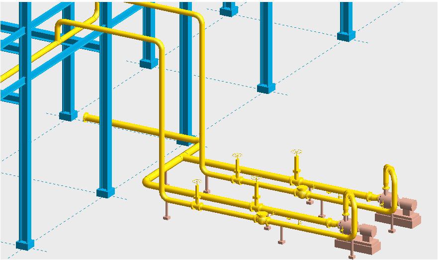
Standard pump piping routing / Arrangements-
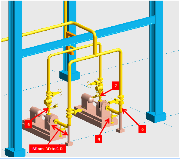
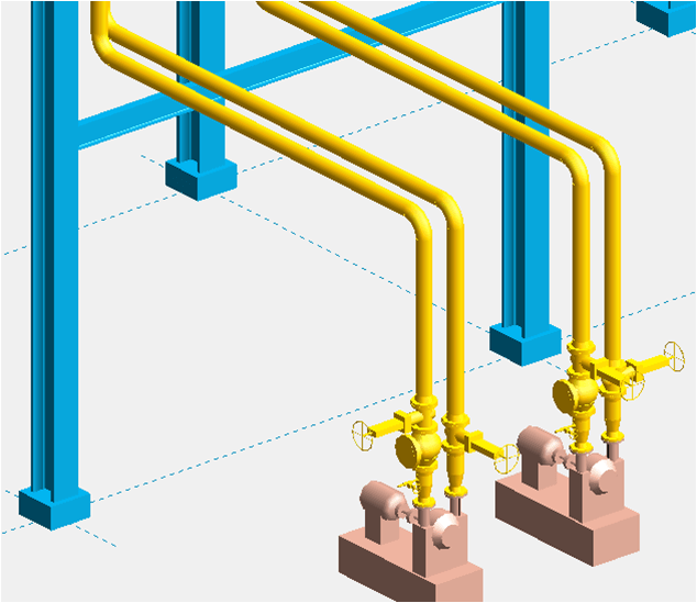
“Arrangement A1” above is considered for medium sized pumps having suction line size around and below 10 inch. The suction strainer is placed between the isolation valve and flange. Suction Line is supported with trunion and from structures available above. Discharge line is taken vertically to clear headroom and supported from above. Concentric reducer if needed is placed in the first removable spool. Check valve and isolation valve are placed immediately after. From pump nozzle to first elbow a minimum 3 to 5 diameter straight length to be there including length of reducer where possible.
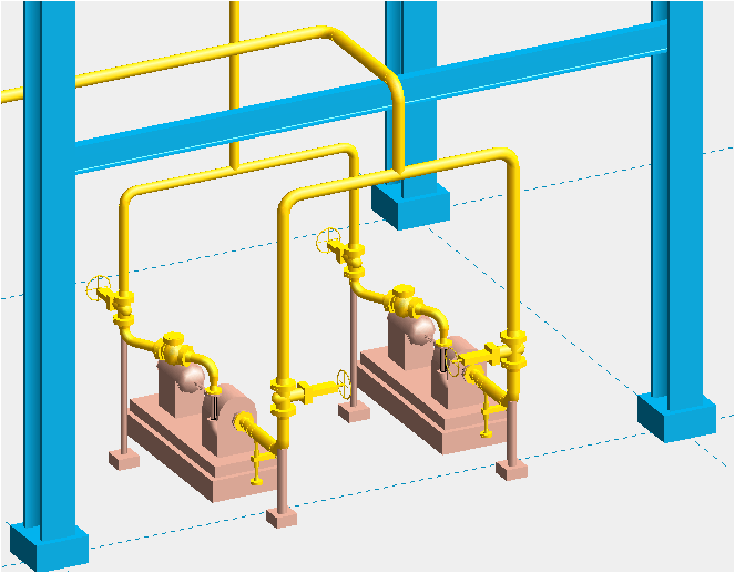
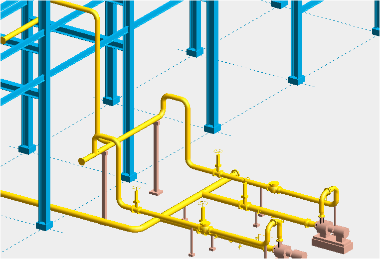
“Arrangement B1” above is an alternate arrangement used instead of “Arrangement A1” (a) For larger line sizes with higher pressure ratings when the block valve hand wheel becomes too high to operate. (b) When check valves to be installed in horizontal position for e.g. lift check valve will work in horizontal position only.
Here the discharge line is rolled as suitable so that the supporting will come out of foundation area. And the line is supported with trunion at elbow.
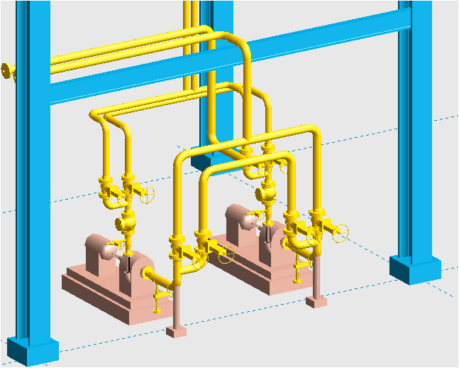
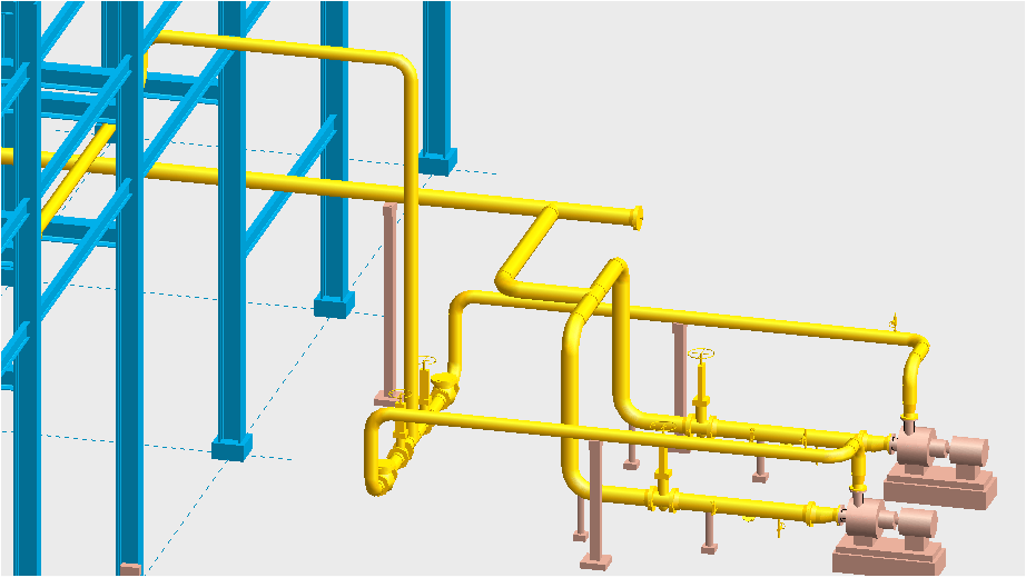
In similar fashion “Arrangement C1 & D1” are used when the pump is used for two different services. Here on suction line the service B line is connected after main isolation valve for service A as shown above. And on discharge line it is connected after the common check valve.
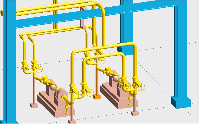
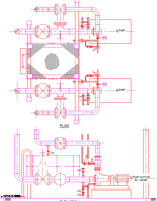
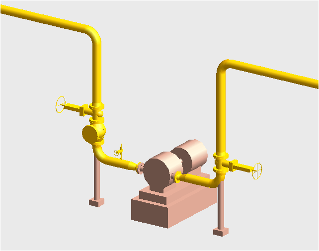
“Arrangement E1” above is used for larger pumps and for critical services where straight length requirement is anticipated. This arrangement also is more operation and maintenance friendly. Suction and discharge Lines are supported from floor.
“Arrangement F1 & G1” are slight variation of the previous arrangement which is used for hot lines that require more flexibility. Its a common practise to have a suction and discharge header near pump and branches to and from pump is connected to this header, the above arrangement depict that.
“Arrangement H1” can be followed for larger lines where the valve elevation requires a platform to operate.
“Arrangement J1” is for top suction and top discharge pumps. In both suction and discharge line valves are placed right after removable spools with temporary strainer in between flanges in suction line. The valves in discharge line if required can be placed horizontally as shown in “Arrangement B1”. For dual services the arrangement can be modified as shown in “Arrangement C1&D1”.
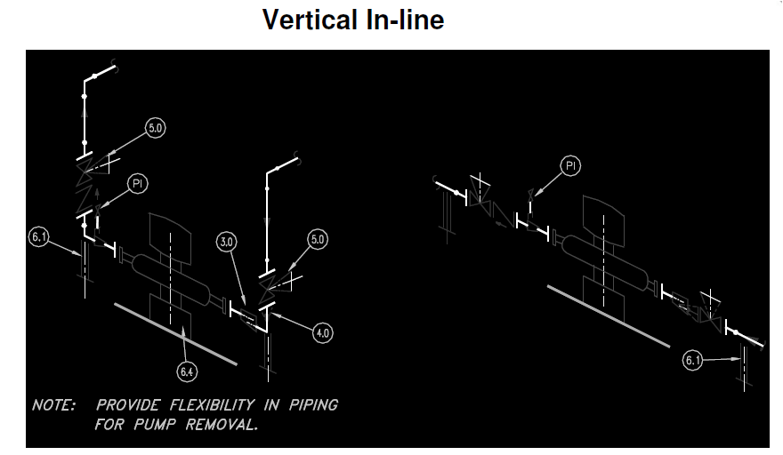
“Arrangement K1” is for Side suction and side discharge pumps. If the line size is bigger the elbow on vertical can be omitted and the whole valves can be arranged in ground level, this helps in supporting also. The routing for vertical pumps is shown in below “Arrangement L1”. For vertical inline pumps “Arrangement M1” can be referred.
Points to be considered while designing pump piping- (Refer Arrangement -A1 for indication of some points below )
1. Final reduction in line sizes to be as close as possible to pump suction nozzle so that pump suction will not be starved.
2. You can use reducing elbow instead of a fitting to fitting connection of reducer and elbow, if the piping spec permits for the same.
3. When reducer are required at suction lines it should be eccentric with flat side on top which will prevent vapour being trapped and encouraging cavitations.
4. Drains are provided for hydrocarbon or hazardous chemical services to drain small quantities of trapped liquid. These drains are not required in water or non-hazardous services. Follow P&ID in any case.
5. While making directional changes or reduction in suction pipe, route it so that there is no high points/low points and pockets where entrapped air can accumulate.
6. To allow pumps to be removed easily if required, flanged removable spool pieces are used on both suction and discharge lines.
7. Pressure gauge should be located on discharge line upstream of the check and isolation valve.
8. Slope towards suction resource to be considered if suction tank/resource is lower than pump suction nozzle.
9. Slope towards pump to be considered when pump is taking suction from vacuum tower.
10. Strainers:
Strainers are used in suction lines to prevent any pipe debris damaging the internals of pumps. These are located between pump isolation valves and pump nozzle. Temporary strainers are used for initial run of pumps. After the pump has run for several days the block valve can be closed and temporary strainer is removed.
(a) Temporary suction strainers is provided in suction lines 2-1/2” and larger.
(b) Permanent suction strainers is provided if shown in P&ID.
(c) Strainers are available in the following styles: Flat, Basket, Conical and tee type. (See fig-N1). Conical strainers are longer than the basket types so sometimes it is difficult to insert it in fitting to fitting arrangements. Flat strainers have very less opening area and small amount of debris will restrict the flow even more so flat strainers are specified for very short suction lines where very less debris is expected.
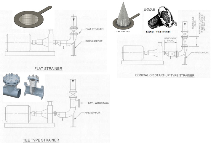
(d) For the flat, conical and Basket types a removal spool piece should be provided which can be unbolted when strainers need to be removed for maintenance. For Tee type filter element can be removed inline without the need to unbolting the whole line and it does not affect the pump alignment. This is the reason why Tee types are preferred in many cases.
11. Valve:
(a) Valve hand wheels whenever possible, to be contained within the perimeter of the pump foundation. It shall be oriented such that, it will not interfere with pump maintenance and operation.
(b) Pump valves are operating valves. it should be arranged such that it can be operable from grade or platform. Isolation valves must be provided upstream of the strainer on suction line and to be located within 3 metres from pump nozzle.
For more information on valve access distance please see https://thepipingtalk.com/2019/04/valve-accessibility-and-clearance-distance/
(c) Check valves can be installed in vertical or horizontal position, except lift check valve which shall be in horizontal position only.
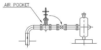
(d) If gate valve has to be installed on the suction line of a pump which takes suction from below, the valve stem shall be horizontal so that there should not be any scope for air pocket (see fig-O1).
12. Straight length requirement:
(a) When suction piping is in horizontal plane provide a minimum of 3 to 5 diameter of straight pipe between the pump nozzle and the first elbow. Eccentric reducer may be included in this straight section.
“The important thing to note here is that, straight length requirements are preliminary and for precaution, the same can decrease or increase according to vendor requirement”
(b) For double suction pumps the immediate elbow from suction nozzle should be in vertical direction if at all possible. Where it is necessary for some reason to use horizontal elbow, it should be a long radius elbow and there should be a minimum of five diameters of straight pipe between elbow and the pump suction (see fig-P1).
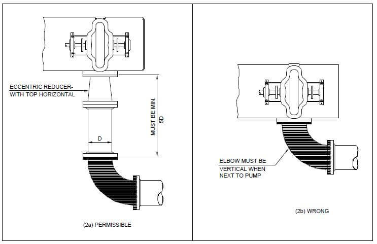
(c) For top suction, pump elbow shall not be connected directly to the pump suction flange. Straight piece of minimum 5 diameters should be provided.
Below is an image which depicts the above.
13.Supporting:
(a). Suction lines shall be supported adequately to ensure compliance with allowable loads and forces on pump nozzles.
(b) The suction line usually is supported under the elbow with a trunion support. Discharge line can be supported from top, taken from structure/racks available nearby. For hot lines spring supports are used as per stress review.
(c) Avoid supporting very large lines from pipe rack structures if possible, this enables minimum sized beam sections to be used and batter access To pump removal and maintenance.
(d) To avoid overload on pump nozzle due to thermal expansion of piping the below items shall be applied
# Absorb thermal expansion by piping route
# improves method of support.
# install expansion joints. (This method only use when unavoidable)
(e) For hot services when one pump is standby connecting branch to it will be cold while the branch connected to operating pump will be hot. There will be temperature difference between both the branches. This has to be considered while routing and supporting pipe.
(f) If support is installed very close to suction or discharge nozzle, it shall be adjustable type so that pump centring can be convenient.
(f) Support installed around suction and discharge nozzle shall be such type that it can be dismantled and piping can be removed conveniently during pump maintenance.
Antony
Demonstrated very well.
🙂
Canada Piping Engineering Services
Thank you, I have recently been searching for information about
this subject for ages and yours is the best I’ve came upon till now.
But, what concerning the conclusion? Are you sure about the supply?
kumar
At what elevation pump suction line should be place from ground level?
tamil
from low point drain to GL maintain 200mm min.
Heat Pump Thames
All the best information regarding the pump piping arrangements.Such articles are not only knowledge enhancers but also very interesting to read and to learn to compare from. Thank you for this article! This is really very informative for us.Well, I have visited another site Comfortgroup.co.nz having some wonderful and similar information.