What is a centrifugal compressor –
Centrifugal compressor is a dynamic machine. It achieves a pressure rise by adding kinetic energy/velocity to a continuous flow of fluid through the impellers. This kinetic energy is then converted to an increase in pressure by slowing the flow through a diffuser.
How a centrifugal compressor work –
Centrifugal compressor rotor is coupled to a driver for e.g electric motor, steam turbine. The driver rotates the rotor of centrifugal compressor. The impeller which is attached on the rotor also rotates in high speed. This high speed and the design of impeller enable it to throw/drive/propel air from its center to the outside edge creating a vacuum at its center also referred as “eye of impeller”. This vacuum draws air from outside through inlet nozzle. The spinning of impeller increases the pressure of gas considerably. Then the high velocity air from the outer edge of spinning impeller is directed into a diffuser. The continuously increasing shape of the Diffuser decreases the velocity of air eventually resulting in an additional increase in pressure. The pressure rise in impeller is almost equal to the pressure rise in the diffuser.
Please see below video animation available on YouTube which pretty much explains how a centrifugal compressor works.
Parts of a centrifugal compressor –
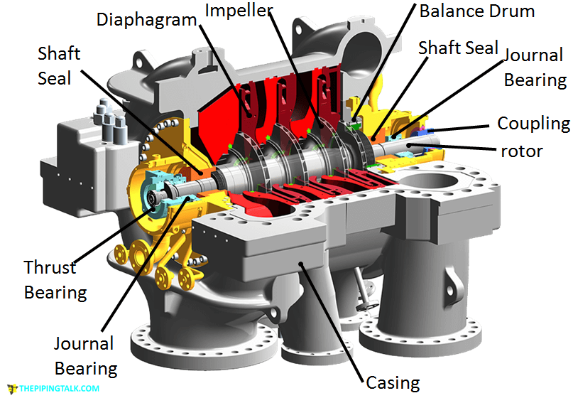
A brief description about all components shown in Fig-1A is provided below.
Casing:-
The casing is the outermost pressure containing part. The casing, the compressor inlet / outlet flanges have to be rated for the maximum discharge pressure of the compressor. Casing is either horizontally or vertical split. See Fig-2A. On a horizontal split casing the top and bottom half are bolted along the centreline. Maintenance of internal part can be done by removing top half. For this most of the piping connections are given on the bottom half of the casing, so that maintenance can be done without removing connected piping. However the main process connections may be located in either top or bottom half.
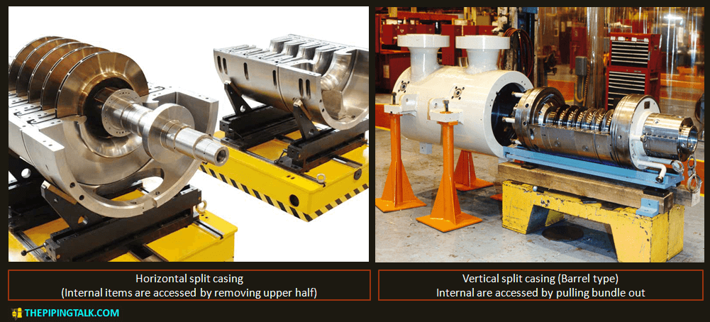
Vertical split casing often called barrel type have a complete cylindrical outer casing. The internal items like rotor assembly are fitted into it by rolling it inside and then the cylinder is closed along both sides by bolting.
Horizontally split casings are used for low pressure application up to 40 bar (600 psi) discharge pressure. Vertical split casing (Barrel type) is used up to 800 bar (12,000 psi). Multistage compressors casings are mad from carbon or high/low alloy steel material that is either cast or fabricated from casting, forging, plate or a combination of these.
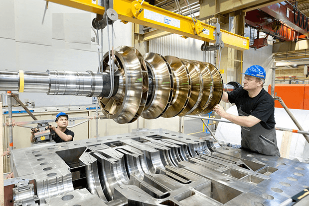
Rotor:-
Rotor of a centrifugal compressor is assembly of shaft, impellers, balancing drum, thrust bearing collar, the coupling hub, sleeves and spacer rings.
Shaft:-
The shaft is a stiff section usually made of 40NiCrMo7 material. It is machined and impellers and spacers are mounted on the central part, bearings and seals are mounted on both ends.
Impellers:-
The impeller is the main rotating element of compressor, which adds velocity to the gas. The shape and size of impeller affects the head and flow characteristics of the compressor. Impeller is of three types:
(a) Open impeller: These have no enclosing covers either in front or back side. Open impellers are used for large flow rates on a single stage compressor. These are not typically used in process industry other than air compression and occasionally as the first stage of a multistage compressor.
(b) Semi enclosed impeller: These have one side enclosed and one side free. The shroud (enclosing plate) adds mechanical strength. They have higher efficiencies than open impellers. These are also used for large flow rates in single stage compressor and as first stage in a multistage compressor.
(c) Enclosed impeller: Here the vanes are located in between the 2 discs. These are mainly used in multistage compressors. The backward leaning, closed impeller which has a wide flow range is the most commonly used impeller.
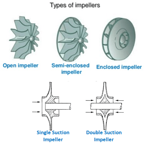
According to how the impeller takes the gas in, impellers can further divided into
(a) Single suction impellers: It takes the gas in axial direction on one side of impeller only.
(b) Double suction impellers: It takes the gas in axial direction on both sides of impeller. These are equivalent to two single inlet impellers placed back to back and it can handle twice the flow at same head as single inlet impeller.
Diaphragm:-
Diaphragm is the stationary element inside casing. It includes the diffuser for the gas as it leaves the impeller and a channel to redirect the gas through return passageway into the next impeller. It is fabricated or made by casting. These are halved for ease of rotor installation. In vertical split–barrel type compressor the diaphragm halves are kept together by tie-rods thus making up two separate bundles. After installing the rotor they are bolted to each other. The resulting assembly is placed in the casing axially. In horizontal split casing each diaphragm half is singly installed in the two casing halves. The outer surface on each diaphragm has a groove to combine with the corresponding relief on the casing. After installing rotor and other components in the lower half, the upper half including casing a diaphragm are bolted with each other.
Bearings:-
In a compressor the rotor is held in position axially by a thrust bearing and it rotates on two journal bearings. The journal bearing are located at both end of the rotor and the thrust bearing is mounted outside of the journal bearing and on the side opposite to the coupling. A brief description on both the bearings is provided below.
Thrust bearing:-
Thrust bearings are used to restrict axial motion. Thrust collar is hydraulically fitted with rotor so that it rotates with it. Thrust bearings have a stationary thrust surface, thrust pads and a thrust collar which revolves with the shaft. In normal condition there is a thin layer of oil in between thrust collar and thrust shoe. Any axial motion is prevented by the thrust shoes. See Fig-4A (a) & (b).
Flat land bearing, tapered land bearing are used, but less frequently. Tilting pad thrust bearings are most commonly used.
How a tilting pad thrust bearing work:
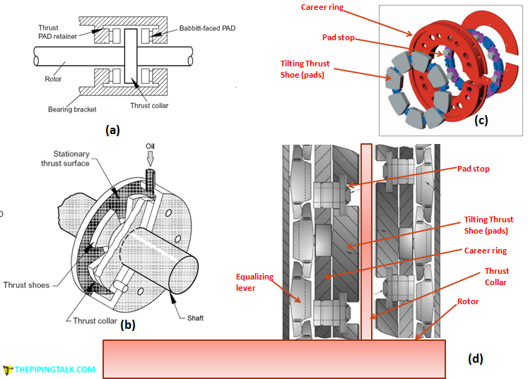
As you can see in fig-4A (c) & (d), the tilting pad thrust bearing consist of a career ring which holds the thrust shoe. Any axial movement from the shaft collar is prevented in either direction due to the presence of thrust shoes. When only some of the thrust pads receives axial movement load from the thrust collar it will pass this to the equalizing levers. All the equalizing levers then readjust such that all pads carry equal load. The inlet and outlet for oil are present in the bearing housing. The oil prevents the thrust collar and thrust shoe to touch in normal condition, thus preventing wear and tear by lubricating it and also helps in taking away excess heat and maintaining the temperature inside bearing housing as required.
Journal bearing (Radial bearing):-
Journal bearings rely on pressurized oil fluid films-that form between the shaft and bearing to support the rotating shaft. The portion of the shaft supported by the bearing is called the journal.
Straight sleeve bearings are used for low speed units with short bearing span. Another type of bearing in use are Pressure-dam sleeve bearing, but the most commonly used is Tilting pad bearings, as they are suitable for resisting unbalancing action of the oil firm.
How a tilting pad Journal bearing work:
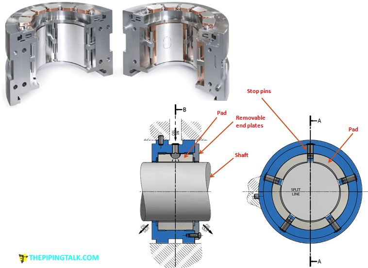
Generally Tilting Pad Radial Bearings consist of 4 or 5 pads located both circumfentitally and radially by stop pins, and axially by end plates. The stop pins also functions as oil supply nozzles. Standard pads are centre pivoted so they are suitable for either direction of rotation. The shaft will be centrally located inside the bearing housing. There will be a small clearance between shaft and the bearing pads. Pressurized lubricating oil is sent to the bearing and the oil will fill the clearance. Because of the oil pressure it will restrict both pad and shaft to contact each other while the shaft rotates. However this will ideally make the shaft float in between achieving a desired contactless bearing with less wear and tear.
Shaft seal:-
Seals at two shaft ends, where the shaft comes out of the casing, are used
(a) To minimize leakage of process gas (which is being compressed), from inside to out of compressor.
(b) To prevent outside air or oil vapour get into compressor and mix with process gas.
Dry gas seals:
Dry gas seals have become the new standard for centrifugal compressor because of their high reliability and utility, environment benefits.
How Dry gas seals work:
Dry gas seals consist of two mating rings: one of them is stationary and the other one is rotating, see Fig-6A (a). When the compressor is not running they are held in close contact through the action of the spring. When the compressor is spinning at high speed it will create hydrodynamic forces and will force the stationary ring against the spring, creating a working gap around 2 to 5 µm between the two rings. External sealing gas which has slight higher pressure than the gas inside compressor is sent to the sealing system. This sealing gas will pressurize and seal the space in between the rotating ring and the 1st labyrinth (adjacent to process gas side). Most of it will pass to the inside of compressor but due to the restriction presented by labyrinth the process of escaping into compressor will be very slow and there will always be a positive pressure inside the seal system. The balance sealing gas will travel through the working gap and will act a working fluid. As the working gap is very thin the sealing gas escaping through it will be very less. Whatever Sealing gas escaping through this, will be sent to a vent system.
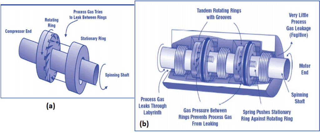
This arrangement also needs no lubrication because both the rings do not touch each other. The stationary ring is sealed inside sealing case by use of o rings. Putting two or more of these Dry seal arrangement in series is called “tandem dry seals”.
Tandem Dry gas seals working:
Tandem gas seal being considered here has two of the dry seal system discussed above in series in a single cartridge. The 1st one is called primary gas seal, any leakage from this is vented to a vent system. The 2nd one is called secondary seal and these acts as a backup if the primary seal fail.
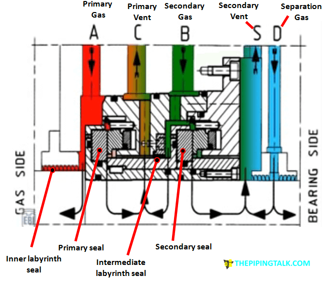
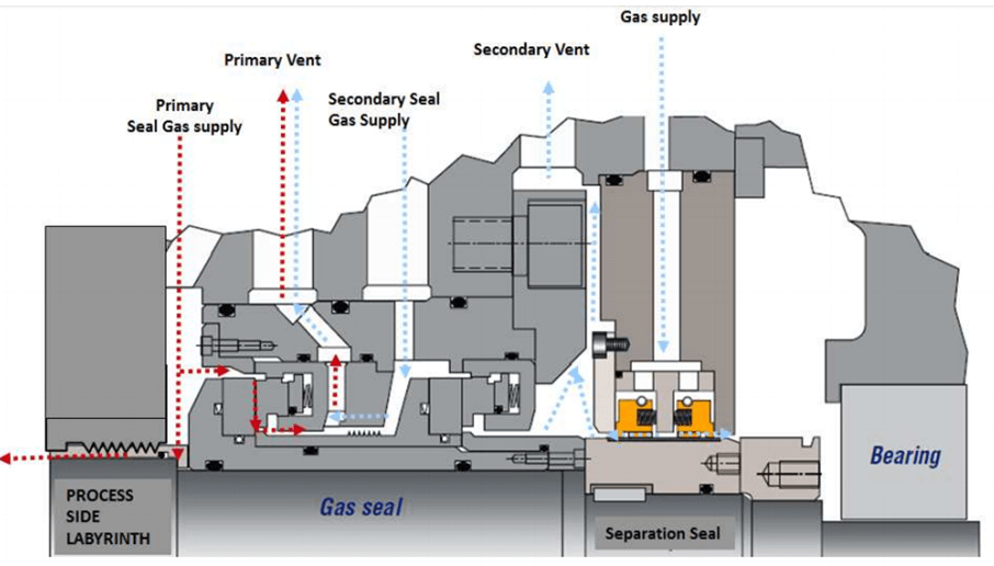
Inboard of the dry gas seal is an inner labyrinth seal, which separates the process gas from the gas seal. External primary gas is supplied to primary seal as discussed most of these will pass into compressor and very little amount will pass between the rotating and stationary face and then it will be vented into primary vent. Secondary gas is supplied to secondary seal. Some of it will pass through the intermediate labyrinth and will be vented through primary vent. This action will also block primary seal gas to pass inside secondary vent through the intermediate labyrinth. A little amount of the secondary seal gas will also travel through the gap between the rotating and stationary face element present inside the secondary seal and eventfully vented through the secondary vent. Adjacent to this seal cartridge on compressor shaft there is bearing housing. To prevent the lubricating oil to pass inside the sealing system and mix with the process gas the separation/ barrier gas is supplied. The separation gas pressure will prevent oil to enter through the labyrinth adjacent to the bearing housing and, some amount of it will pass through the inner labyrinth and vented through the secondary vent. Fig -8A shows the path of seal gas inside tandem seal .
While discussing Dry gas seal we came across is labyrinth seal. A short description is provided below for it.
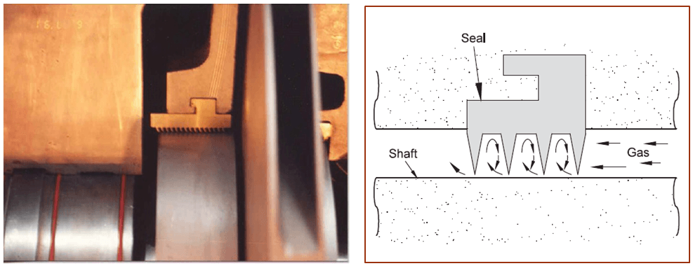
(b) Labyrinth seals-
Labyrinth seals have many sharp edged ridges machined on the outer diameter of rotating shaft or inner diameter of the shaft seals. Labyrinth seals may be either rotating or stationary. Sealing is achieved by the pressure drop across each ridge as a small amount of gas is allowed to leak. The sealing action is a result of flow resistance by reducing it gradually across the labyrinth teeth.
Balance drum:-
In a centrifugal compressor since the pressure on the discharge side will be greater than the pressure at the suction side there will be a net axial force or thrust acts towards the suction side. This net axial force will be discharge pressure Pd- suction pressure Ps.
To explain it clearly Ps-suction pressure acts on the impeller and at it is increased to P1 at the impeller tip. P1 will act on the suction side of 1st impeller and fully on discharge side of 1st impeller and then on the suction side of 2nd impeller. At the tip of 2nd impeller it will convert to P2 and the cycle will follow till discharge impeller.
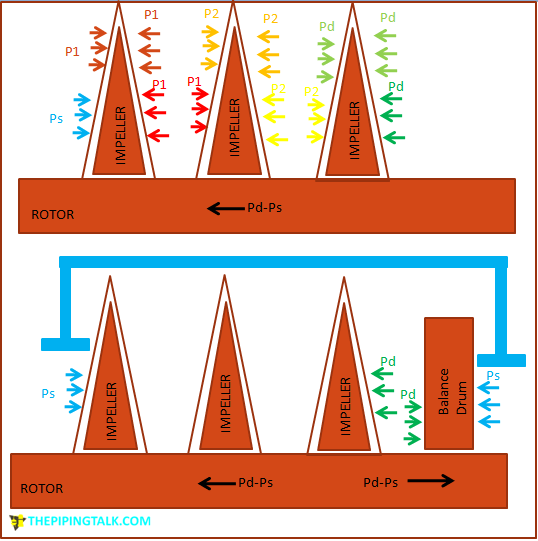
As you can see in Fig the forces shown in similar colour will cancel each other out and there will be a net axial force Pd-Ps acting on the shaft towards the suction side. If this force is very less the thrust bearing can restrict this. But as in many cases for multistage compressor the net axial force will be large.
Now to counter it a balance drum is added on the discharge side. The discharge side of the balance drum is connected to the suction side through an external pipe spool so that on the discharge side it will have the pressure equal to the suction Ps. Also on the other side of the balance drum now the discharge pressure Pd will act.
As you can see in figure by adding this arrangement we will have another net axial force Pd-Ps. As this net force will act on the opposite direction towards discharge, it will cancel out the previously derived Pd-Ps acting towards suction. Whatever remaining forces generated due to other reasons can now be taken care by the thrust bearing.
Coupling:-
The coupling transmits power from driver to the compressor. Coupling can be direct or through a speed increasing gear. Usually, toothed couplings are used with force-feed or filling lubrication. The couplings with force-feed lubrication are designed for high speed of rotation and for the most part they only are used in compressors. Another type of couplings is sealed, generally with lubricating grease to be filled every so often; these couplings are used only on slower speed drive shafts.
The video collected from you tube below explain parts of a centrifugal compressor in detail and you can see in real the parts and where it goes during assembly. The video is little long but completely worth your time.
https://www.youtube.com/watch?v=Vuc1e4ee7To
References:
Maurice stewart, 2019, Surface production operations-Volume IV-pumps and compressor,Gulf professional publishing
Paul C. Hanlon, 2001, Compressor Handbook, McGraw-Hill,USA
Saeed
I am learning to much about compressor & about his parts detail information. Thanks.
Mumtaz Ahmed
Thanks for your your information about centrifugal compressors and refreshing my memories
RAJEEV singh
Very good details
bittra.ramesh
thank you very good details
bittra.ramesh
very good details but i need some details all all elements and readings please sendme thank you .