The location of reactor, tanks and other large equipments are decided from beginning of project, some of these location also comes from the process licensor and other similar reference project which the epc company has done before. for above cases as we are not that flexible to change its location, but for other equipments like pumps, heat exchangers, filters and other facilities the piping engineer is held responsible to decide its location.
Here we will look at some very basic ways we need to follow for deciding the location of these equipments.
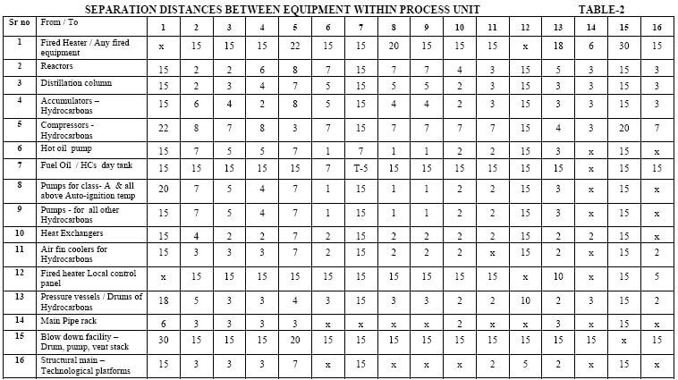
1. Plant layout specification:
This document is developed by the epc company after following codes and standard like OISD-118, GE GAP 2.5.2, PETROLEUM RULES/ACTS etc .In this document the floor spacing required for equipments and safe distance between process equipments and units are highlighted .This distances need to be followed.
2. Economic piping:
(a).Take a process flow diagram; identify the alloy or heavy wall piping.
(b).Divide the PFD into smaller group of process related equipments.
(c).Arrange the equipments with in this subsystem according to process requirement and economic piping rules.
(d).Then arrange all the subsystems within the plot boundary to have a batter interconnection.
This exercise is done to check the length of alloy or heavy wall piping to a minimum by properly locating the equipments thus reducing the overall cost.
3. Process requirements:
While deciding location of equipments process requirements like gravity flow and minimum pressure drop requirements to be taken care of.
For e.g if there is a main header for drain line where we need to connect the equipments drain, then the equipments location should always be above the elevation of common drain header. Same rules apply for flare lines and related equipments e.g psv should be located above flare lines elevation for draining purpose.
Similarly if there is a minimum pressure drop requirement for a pump then we need to place it as close to the suction source.
4. Common operation:
Equipments that require continuous operator attention and share common utilities and maintenance facilities should be grouped together. Like a set of pump, a set of related heat exchangers.
5. Equipment size:
First place the odd and big shaped equipments in the plant and then plan the reminder of unit around them.
5. Underground facilities:
We have to investigate what systems are placed underground and their location before proceeding for equipment location. Many foundations extend over underground and they have varying shapes and piles underground which the designer should see either in the model or respective civil foundation drawing before locating the equipment.
The foundation length of Two equipments is also to be seen so that they do not foul with each other.
5. Climate condition:
Heavy rainfall and wind direction can affect the equipment location. The location of furnace, cooling tower, flare, and incinerator are decided by the wind direction and location of effluent plant is decided by the grading of plot.
5. Pipe rack location:
Location of pipe rack to be seen before deciding the location of facilities as its the main interconnecting system between process Units. How we are going to feed process and utility connection to the equipment from main pipe rack will always affect the location of equipments.
Alfonso Ruiz
Es muy importante conocer entradas y salidas, distancias de materias primas. Igual para productos terminados e intermedios. Decisivo también ubicación sistemas de drenajes y venteo