
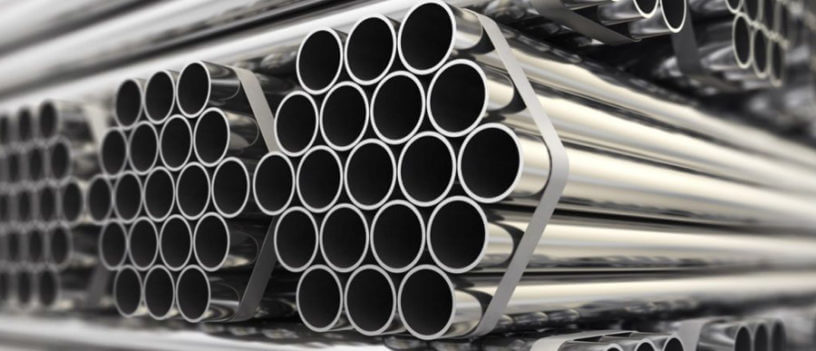


Process plants deal with fluids those are mostly chemical in nature with varying pressure and temperature .these fluids are transported from one point to another through pipes. The operations must be leak free.
Plants are designed for certain no’s of years, most commonly for around 20 years. In these life cycle years it shall contain
1. The fluid with varying temperature and pressure,
2. Corrosion due to fluid and outside environment,
3. Stresses generated due to plant operation
And it must not fail.
To satisfy these, the material used to build a pipe must have high strength and ductility besides other properties like resistance to corrosion, commercial availability etc. There comes metal into picture and that is the reason why we see most of the pipes used in plants being metallic rather than plastic or rubber. As a matter of fact plastics and rubber are also used but not as common as metals.
So after the designer has chosen the material of pipe a question comes how much thick should be the pipe so that it will satisfy previously said conditions.
ASME has laid down the Procedure to calculate this. We will explore this with an example and detail calculation.
As per ASME B 31.3 – Para 304.1
The required thickness of straight section of pipe shall be determined by following equation (1a)
t_{m}= t + cWhere tm = Minimum required thickness
t = pressure design thickness
c = mechanical allowance (thread and grove) +corrosion and erosion allowance
to calculate t = pressure design thickness in above it has given formulae in para 304.1.2
that says for t ≤ D/6 the internal pressure design thickness for straight pipes shall not be less than the calculated in accordance with either eq (3a) below or (3b)
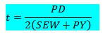
t= \frac{PD}{2(SEW+PY)} \hspace{1cm} \textbf{:equation 3a}Where P = Internal design pressure (psig)
D = OD of pipe (in)
S =Stress value from material table A-1 B31.3 (psi)
E = Weld joint quality factor from Table A-1a (for casting) or A-1b (for tube/pipe)
W = Weld joint strength reduction factor from Para 302.3.5.e
Y = Temp dependent co efficient from Table 304.1.1
t= \frac{P(d+2c)}{2[SEW-P(1-Y)]} \hspace{1cm} \textbf{:equation 3b}The primary equation for calculating the pressure design thickness of straight pipe in ASME B31.3 is Equation (3a), which uses the pipe’s constant outside diameter (D). This is the standard method in the piping industry because the OD of a given Nominal Pipe Size (NPS) is fixed, regardless of wall thickness (schedule). This allows for direct calculation of the required thickness.
Equation (3b) (above) is seldom used and its used as a reference to verify/double check . So equation (3b) is an optional alternative provided for specific situations or academic purposes where working with the inside diameter (d) might be necessary or preferred, such as when matching calculations to pressure vessel codes which traditionally use ID-based formulas. The code notes that Equation (3b) will provide the same required thickness as Equation (3a) if applied correctly.
EXAMPLE:
Now we will determine the required pipe thickness for a pipe
With fluid design temperature = 260°F
P = Design Pressure = 150psig
D = Pipe OD = 30in
Pipe material = A106 grade B (seamless)
C = Corrosion allowance = 0.125in
Mill tolerance = 12.5%
So to put in Equation 3a we know value of P,D only. Lets see how we can determine other values from code
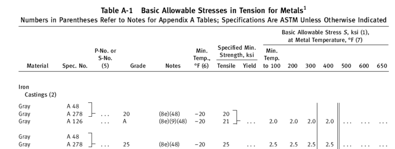
S =Stress value from material table A-1 B31.3 (psi)
Go to table A-1 ,you will find this
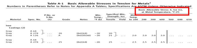
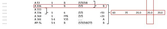
Now scroll and find carbon steel pipes and tubes where u can find A 106 gr B

This table gives the allowable stress value of materials at a temprature.
After finding the material grade row find the °F temperature column. And as shown above here you can find the allowable stress value S in (ksi) for A106 gr B for 200°F to be 20 ksi = 20000 psi.
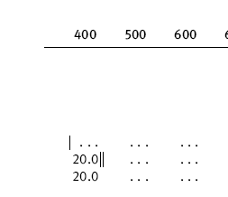
For more temp scroll next page;
A single bar as shown below specifies the usage of material beyond this temperature needs special precaution.
A double bar as shown below prohibites the usage of material beyond this temperature

Screen shot of scrolled page as below for reference.
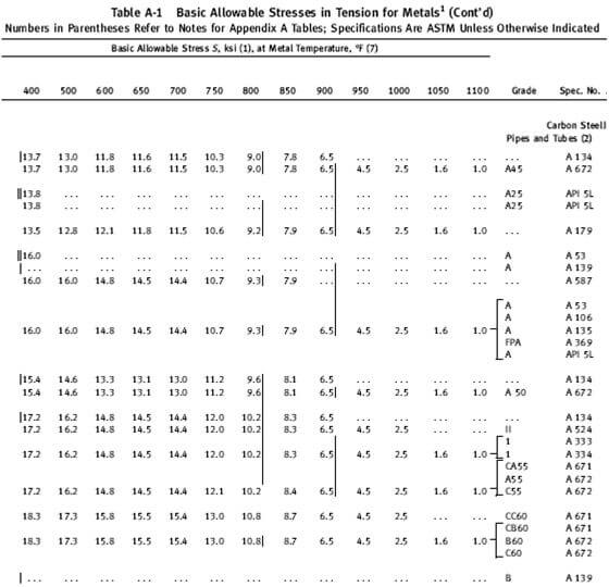
Allowable stress value for material in between the temperature specified in the chart can be interpolated.
That explains how to find S value for given material.
For our example we have got S = 20000 psi
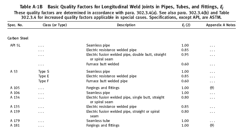
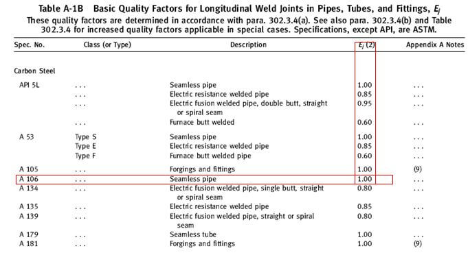
E = Weld joint quality factor
Go to table A-1b
Find the material grade and find Ej value as shown below for our case its 1.0 so
We got E=1
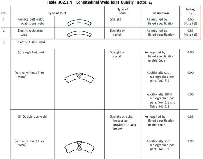
W = Weld joint strength reduction factor
Read para 302.3.5.e and then go to table 302.3.4
If the pipe is welded i.e not seamless then you have t multiply the value given in para 302.3.4 (Ej) with the above determined (E)
As our pipe is seam less the W value becomes 1.
If our pipe grade specified as Astm A 135 Electric resistance welded then W value would be 0.85 as shown below.
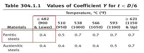
Y = Temp dependent co efficient
Go to table 304.1.1
As A106 gr B is ferritic steel go to ferritic steel row .And then find the temp column for your temperature.
below 200°F the value of Y as shown below is 0.4
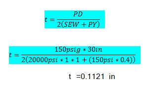
Now that we have got all the values lets put it in the equation 3a
t= \frac{PD}{2(SEW+PY)}t= \frac{150 psig * 30 in}{2(20000psi*1*1+(150psig * 0.4))}t=0.1121in
Putting the value of t in equation 1a tm = t + c
tm = 0.1121 in + 0.125 in = 0.237 in
this is the required minimum thickness after mill tolerance of 12.5% means the specified thickness by the designer may decrease 12.5% during the manufacturing process and even after reducing 12.5% pipe thickness should not be less than tm i.e 0.237in
So 100%-12.5% =0.875% = 0.237 in
t required = 0.237 in /0.875 =0.270 in = 6.858mm
as we will not get commercially available 30 in pipe with 6.8 mm thickness we have to go to b36.1 or any pipe thickness chart on net and choose the schedule thickness which is nearest to the calculated value
in this case its 30 in schedule standard whose thickness is 9.53 mm
************end************
Leave a Reply