What Is a Machinery Foundation and Why It Matters?
A machinery foundation is a specially designed concrete structure that supports machines, transfers their loads safely to the ground, and controls vibration during operation. A well-designed foundation is critical for machine reliability, alignment accuracy, and long-term structural safety. Below is an overview of how the main components of a machinery foundation work together as a system.
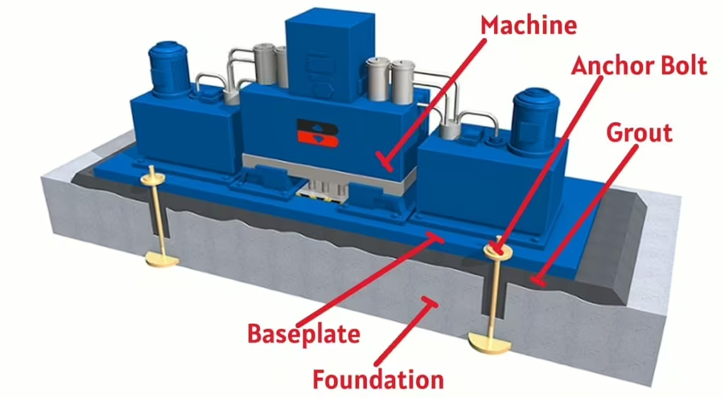
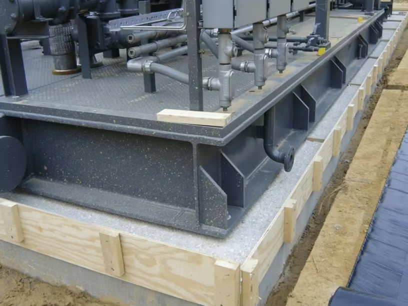
A baseplate is used in skid-mounted rotating equipment, such as pumps, compressors, and turbines, to spread the equipment’s weight and operating forces over a larger area of the concrete foundation. This helps prevent local overstressing and is essential for maintaining alignment and controlling vibration in rotating machinery.
The baseplate is anchored to the foundation/ with anchor bolts to resist vertical and horizontal loads during operation. Although the foundation surface is intended to be level, in practice, concrete surfaces have unevenness that is difficult to correct accurately.
To address this, the baseplate is leveled above the foundation using leveling nuts or shims, creating a small gap between the baseplate and the concrete. After proper leveling and alignment, this gap is filled with non-shrink grout.
Once cured, the grout provides uniform contact between the baseplate and foundation, ensuring effective load transfer, increased stiffness, reduced vibration, and stable long-term alignment of rotating equipment.
Here’s a quick video walkthrough covering this topic in detail
Now let’s break this down in detail
Types of Machinery Foundations
Some types of foundations used for machinery are described below.
Block-type foundation
A block foundation is the most common type of machine foundation used for heavy rotating or reciprocating machines like compressors, turbines, generators, pumps, and diesel engines. Here, the dynamic machines are preferably located close to grade to minimize the difference between the machine dynamic forces and the center of gravity of the machine foundation system.

It is basically a solid mass of concrete (rectangular or square) placed directly on soil to:
- Support the static load of the machine
- Absorb and damp dynamic forces and vibration
- Prevent excessive settlement and resonance
Typically, the foundation weight is kept 2 to 5 times the machine weight, and proper soil bearing capacity is essential to limit settlement and ensure stable performance. So, this type of foundation has a large mass and small natural frequencies.
For compressors and reciprocating type of machines, block type foundation are generally used.
Box-type foundation
A box-type foundation is a modified form of a block foundation in which the concrete mass is arranged as hollow cells or box-like walls instead of a fully solid block. It is used for heavy machines where a large foundation mass is required, but concrete volume and cost need to be reduced. The walls and slabs together provide sufficient mass, stiffness, and vibration damping, while the hollow portion does not significantly affect dynamic performance when properly designed. Machines are mounted on the top slab using anchor bolts and grout. This type of foundation has less mass but more natural frequency than a block-type foundation.

Box-type foundations are commonly adopted for large compressors, turbines, and generators where economy and accessibility are important.
Wall-type foundation
In a wall-type foundation, mass and stiffness are provided mainly by vertical reinforced concrete walls connected by a top slab. The walls act as deep beams, providing high rigidity and effective vibration control, while the open space between them reduces concrete quantity and allows access for inspection and maintenance. The machine is mounted on the top slab using anchor bolts and grout. The vertical and horizontal members of the foundation can also be constructed using material other than concrete.

Steam turbines have complex foundations that may consist of a system of walls, columns, beams, and slabs. It is typically used for long or large machines such as reciprocating compressors, engines, or turbines, where the load is distributed along the machine length.
Frame (Table-Top) type foundation
A frame type (table-top) foundation is a machine foundation in which the machine is supported on a vertical column having a horizontal frame at its top. A frame-type foundation controls vibration mainly by being stiff, not by being heavy. Because it has less mass, it can start vibrating easily if its natural vibration frequency is close to the machine’s running speed. Therefore, a detailed vibration analysis is necessary to make sure the foundation’s natural frequency is well away from the machine operating frequency, so resonance is avoided, and the machine runs smoothly and safely.

It is commonly used for high-speed rotating machines such as steam turbines, turbo-generators, and compressors, where accessibility, ventilation, and reduced foundation mass are important.
Frame type foundation with isolators
One variant of the frame type foundation is with isolators where isolators like springs and dampers are located at the top of the supporting column to minimize the response of dynamic loading. The effectiveness of the isolators depends upon machine speed and the natural frequency of the foundation.

Common term Vs ACI351 Classification
| Common Term | Brief Description | ACI 351 Classification |
| Block Foundation | Solid mass concrete foundation resting on soil; vibration control mainly by mass | Block Type Foundation |
| Box Type Foundation | Hollow or cellular concrete block providing required mass with reduced concrete volume. | Block Type Foundation |
| Wall Type Foundation | The foundation mass is formed mainly by reinforced concrete walls and a top slab. | Block Type Foundation |
| Frame (Table-Top) Foundation | Machine supported on columns and beams with a rigid top deck; vibration control by stiffness | Table-Top (Frame) Type Foundation |
| Frame Foundation with Isolators | Frame foundation with vibration isolators between the machine and foundation or at supports | Table-Top (Frame) Type Foundation with Isolation System |
Foundation Anchor bolts
Foundation anchor bolts connect the machine and its base frame securely to the concrete foundation, transferring operating loads safely into the structure. They are critical for maintaining alignment, resisting vibration, and preventing movement during machine operation. There are two methods to install a foundation bolt.
Pre-installed foundation bolts
Pre-installed foundation bolts are cast into the concrete during pouring. Most standards classify headed anchors (with a nut or plate at the end) as cast-in fasteners, so their position must be fixed accurately before concreting. This is usually done using a steel template plate, which holds all bolts in the correct location and alignment until the concrete sets. these are called cast in foundation bolts.

Some other type of preinstalled foundation bolts are shown below
Sleeve welded to reinforcement bar: (Left side arrangement) A metal sleeve is welded to the reinforcement bars. The bolt is inserted through this sleeve, and its bottom end is stopped and held in place using a metal plate. Instead of a hammer-type bolt, a bolt with a round plate and nut at the bottom can also be used.
Hole left in concrete: (Right side arrangement) A round hole is left in the concrete. The bolt is inserted through this hole and fixed at the bottom using a plate and nut. The plate and nut are tightened from an opening on the outside of the concrete. Sharp corners in the concrete are avoided to prevent cracking.
Post-installed foundation bolts
Post-installed bolts are used when exact bolt positions cannot be guaranteed before concreting. In this method, bolt pockets are made in the concrete, the bolts are installed later, and the pockets are filled with cement grout or epoxy grout.

Method 1: Drilled pocket after concreting
Cylindrical holes are drilled in the concrete after it has set. Hole surfaces should be roughened to improve grout bonding. Reinforcement must be located so it is not damaged during drilling.
Method 2: Pocket formed during concreting
Temporary material (like wood) is placed before concreting and removed later. Conical pockets are preferred as they give better grout bonding. Removal of temporary material can sometimes be difficult.
Anchor bolt types
Plate-type foundation bolts
Plate-type foundation bolts are anchor bolts provided with a steel plate fixed at the embedded end to improve anchorage in concrete. The plate increases the bearing area, allowing the bolt to safely resist high tensile and shear forces from machines. These bolts are usually pre-installed (cast-in) during concreting and are held in the correct position using a template. Plate-type bolts are commonly used for heavy machinery and dynamic loads, as the plate provides reliable load transfer to the concrete and reduces the risk of pull-out.

Canister bolt
A canister bolt is useful in repair work when old anchor bolts need to be replaced, but the concrete cannot be broken deep enough. In this method, a core-drilled hole is made in the concrete, wide enough to insert a steel canister, which is then fixed in place using epoxy. The bolt is connected to the canister at the bottom, and the canister acts as a sleeve. When the bolt is tightened, it creates a holding force by stretching over the free length between the canister connection and the machine frame.

Recommended anchor bolt length
When designing an anchor bolt, it is normally divided into two main parts: the upper section (free stretch length) and the lower section (embedment length).
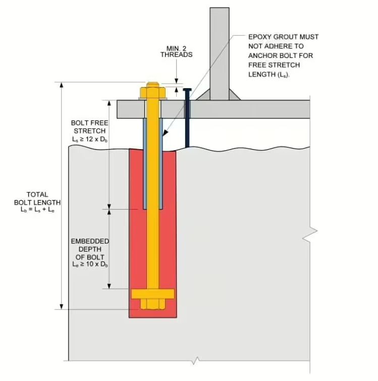
The upper section includes the length of the bolt passing through the base plate, washer, and nut, with at least two threads exposed above the nut, and it must also extend a minimum of 12 times the bolt diameter below the underside of the base plate. This minimum length of 12 bolt diameters is called the free stretch length. This part of the bolt is usually inside a sleeve and embedded in the foundation, but it is isolated from the grout. To achieve this isolation, the portion of the bolt that passes through the grout is typically wrapped with duct tape or foam insulation. This is done so that, when the nut is tightened and torque is applied, this upper section of the bolt can stretch elastically. This stretching is essential because it is how the clamping force is generated to hold the machine base firmly to the foundation.
The lower section of the anchor bolt, called the embedment, is fully encased in concrete or epoxy and is the part that does not stretch or move. Its job is to anchor the bolt securely in the foundation. At the bottom of the bolt, there must be at least a nut to act as an anti-pullout device. However, in most modern designs, a resistor plate is used instead of only a nut. This resistor plate is circular and larger in diameter than the bolt, which helps avoid stress concentrations in the concrete. The plate provides a larger bearing area, so the concrete above it is loaded mainly in compression, which improves holding capacity and prevents bolt movement. Typically, the resistor plate diameter is about three times the bolt diameter, with the plate thickness selected based on the size of the anchor bolt.
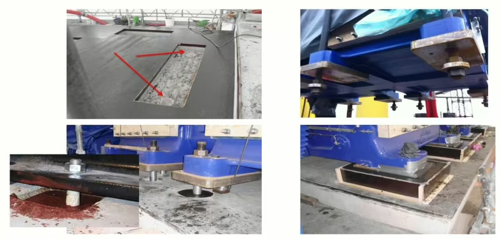
Mounting of the skid to the concrete block
In general, a machine skid can be mounted on a concrete block in two ways. In the first method, shims and metal or epoxy chocks are used, which creates a gap between the skid and the concrete or grout. Because the skid does not have full contact with the foundation, the system becomes more flexible, increasing the risk of unacceptable vibrations. Therefore, this arrangement always requires a vibration analysis to check whether vibration levels are acceptable.
In the second and more common method, the skid is installed on a full bed of grout, so the entire bottom of the skid is in contact with the grout, and there is no gap. This creates a very stiff support, greatly reducing the risk of vibration problems. For this reason, full bed grouting is the preferred and most widely used solution today.

References:
efrc guidelines for vibrations in reciprocating compressor systems
Leave a Reply