
THIS IS PART- Ⅰ OF A SEVERAL PARTS ARTICLE SERIES ON FLARE SYSTEM
petrochemical processing plants generate significant amount of waste products such as methane, volatile organic compounds, Sulphur related compounds etc. These waste compounds are toxic, flammable and corrosive and in many instances cannot be directly discharged to the atmosphere because of reasons listed below.
- Restrictions imposed by local ordinance or plant practices.
- Because of lesser permissible explosion or toxic threshold limit at a particular surrounding for local vents in plant.
- In processes where long and severe waste exhaust temperature is anticipated, the gases cannot be vented locally because of hazardous condition.
“Volatile organic compounds (VOC) are organic chemical that have a high vapor pressure at room temperature”.
In such cases burning this excess hydrocarbon gas is a batter option. For e.g., instead of venting methane to atmosphere we can burn methane which will produce carbon dioxide. It is batter because methane is 20 times more harmful than carbon dioxide towards global warming.
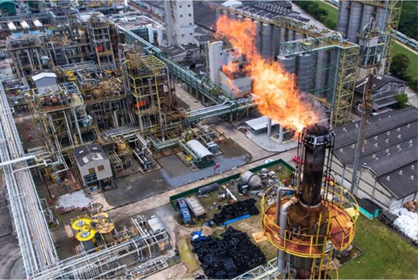
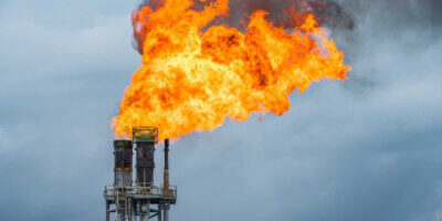
The process of safely burning these waste gases is called flaring. The system that deals with the process and components required to burn the discharge gases in a flare, all the way from blowdown pressure relief devices is flare system.
Flare systems are also designed to relieve emergency process upsets that require release of large volume of gas. Flare systems are currently operated with gas recovery system where the voc gases are recovered and compressed to be used in further processes as a livestock or fuel. When the baseload recovery system is used, the flare (burning of waste gases) is used as a backup and only for emergency releases.
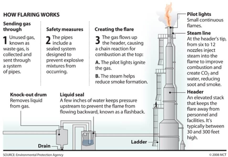
Below animation shows the basic process flow for a flare system. Each element is briefly discussed afterwards.
Flare gas transportation piping-
Waste gases from vents, blowdown gases released from pressure relief devices, are sent to the flare stack through the gas collection header. This piping should be designed to have minimum pressure drop. Potential dead legs and liquid traps are avoided. Use of valves in this line should be kept to minimum and when used should be car sealed to open position. The piping should be equipped for purging so that explosive mixtures do not occur in the flare system either on start-up or during operation. Minimum slope of the flare header shall be 1 :450 (per API 521).
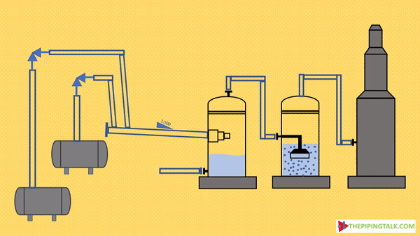
Vessels & Drums used in flare system:
Four types of vessels or drums are typically used in the design of flare systems for specific reasons: those are (a)Knockout drum (b) Blowdown drum (c) Quench drum (d) Seal drum
Knockout drum-
Liquids in the vent system is not desired because of two reasons-
(1) liquid in the event stream can extinguish flame or cause irregular combustion and smoking.
(2) Flaring of liquids can generate a spray of burning chemicals that could reach ground level and create a safety hazard.
Liquids present in the vent stream or the liquid that may be condense out in the collection header and transfer lines are removed by the knockout drum. The knockout drum may either be horizontal or vertical type. A schematic for knockout drum is presented below
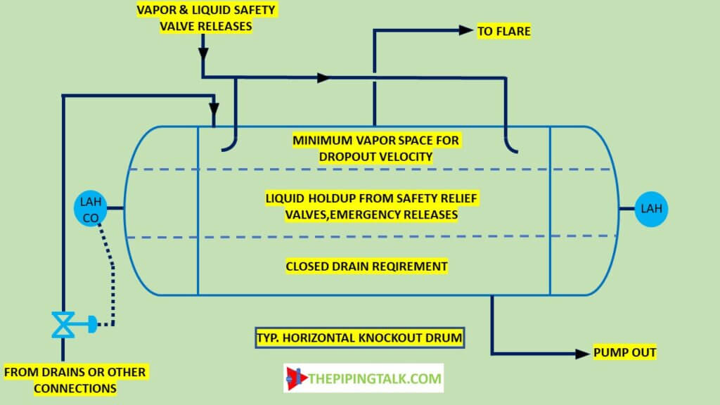
Below is an animation of how a knockout drum works. The two-phase fluid enters the knockout drum. The gas and fluid separate partly first after hitting the deflector plate and for those fluids that still settles at bottom, the gas comes up due to gravity.
A knockout drum is required where enough hydrocarbon liquids are entrained with or condensed from the gas to avoid possible fire hazards from liquid droplets falling out of the flare. The function of the knockout drum(s) may be combined with that of the blowdown drum to provide a single drum, where small quantities of liquid are involved.
The knockout drums may be either horizontal or vertical. Horizontal drums are more common for large relief loads for the following reasons:
(1) The required elevation of the relief header is lower than for a vertical drum.
(2) The horizontal drum would cost less than the vertical drum which has equivalent capacity.
Location of knockout drum is at or close to the flare base, sometime the vertical vessel is located inside the base of flare stack. For this reason, consider the amounts of liquid that may be required to flow though the gas flare header if local or area blowdown drums are not used. The liquid material collected in the knockout drum is usually pumped back to the slop tanks.
Blowdown drum-
Blowdown drum is used when sizable liquid releases from the process is required to be captured. The releases may be intentional like drainage from liquid drain system during shutdown or start up or emergency events like a PSV discharge. The drum must be capable of accepting the anticipated liquid loads without filling beyond the maximum operating level of the drum. This maximum operating level must still provide a gas flow path with sufficiently low gas velocity to allow gravity separation and prevent re-entrainment beyond the design droplet size. Blowdown drums tend to be located near the sources, close to the battery limits of a process unit or area to reduce the amount of piping subject to two phase slug flow. It is not a good practice to design for significant amounts of liquid to run long distances through the plant in the vapor flare header. A sketch of a typical horizontal blowdown drum is provided below.
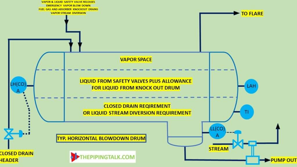
Where the liquid flow quantities anticipated are relatively low, a knockout drum will be sufficient, and a blowdown drum may not be required. Blowdown drums may be advantageous, even for relatively low liquid flow quantities for the following services:
- To collect highly viscous liquids in a relatively small vessel so that the relief header will not become fouled or plugged and the main knockout drum need not be designed to handle this liquid.
- To collect liquids which should not be mixed with other streams due to economic consideration or corrosion potential.
- To collect liquids within process areas where continuous sloping of the headers toward the main knockout drum is not feasible.
Blowdown drums can be configured as horizontal or vertical similar to knockout drum. And horizontal types are more preferred due to same reasons as stated in knockout section.
Where several process units or areas use a common blowdown drum, a combined dedicated liquid relief header from these areas to the blowdown drum should be provided. The separated vapor can then be combined with the vapor relief header. The refinery liquid drain system(s) usually flows to blow down drum.
The horizontal blowdown drum should be sloped 0.33 in per 3.3 ft (0.83 cm per meter) towards the liquid outlet nozzle. A water boot may be required at the bottom of the horizontal drum to remove separated water from the liquid hydrocarbons. The liquid material is usually disposed of to the slop tanks following weathering or directly to refinery process unit. The inlet or outlet nozzles may be installed at an angle from the vertical if the elevation of the flare header is otherwise too low with respect to the blowdown drum inlet nozzles.
Quench drum-
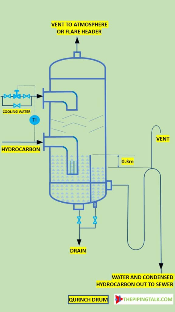
A quench drum can be used to condense the vapor discharge from a relief device for either later return into the process after the relieving condition has passed or for disposal to the sewer. Generally, a quench drum is provided whenever the material being relieved is too valuable to be burned in a flare or too toxic to be relieved to atmosphere in a vent stack. Also, a quench drum can be used to cool hot material so that the entire relief system does not need to be designed for the higher temperature. A third purpose for a quench drum is to quench runaway reactions. A typical schematic for quench drum is presented below.
Seals used in flare system:
A flare system is subject to explosion hazards when air is present in the system. Factors which contribute to air flow into the system are:
(1) thermal contraction of hot gases in the system when flaring stops- When flaring stops, the hot gas cools rapidly and the contracting gas creates a low-pressure zone permitting the influx of air. Rainfall greatly accelerates cooling.
(2) oscillation caused by rapid closure of a spring-operated safety relief valve- Oscillation is caused by the rapid closure of a spring-operated safety relief valve. The column of gas in the header continues to travel under its own momentum and creates a low-pressure zone behind it. As the column recedes, air is drawn into the stack.
(3) velocity of air passing over the top of a stack- Wind over the top of a stack increases air flow with a resultant drop in pressure, which causes gas to be drawn from the stack. Air flows in to replace the gas at a rate that increases with higher wind velocities.
Gas seals for flare system-
Gas seals should be provided on all flares. Gas seal types can be divided into two categories:
Baffle type gas seal-
are known by numerous other vendor specific names such as Integral velocity seals, Airrestor, Reactive, Orifice, Integral Type seals.
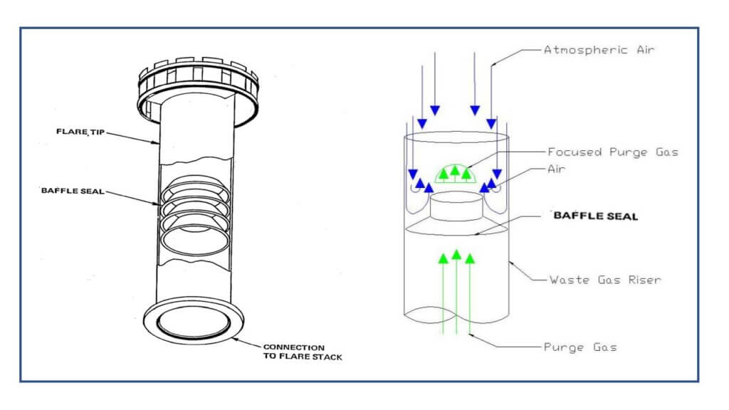
This seal allows flow in one direction with little resistance. However, reversal of flow results in very high resistance. This means that gas can flow out of the flare stack but the counter flow of air back into the stack is greatly restricted. The baffle type of gas seal consists of a series of fixed baffles, shaped like open-ended cones, mounted within a flare tip. Each succeeding baffle of the seal encountered by purge gas traveling up the stack has a larger aperture than that below it. Air attempting to enter the stack is turned back against itself by the first baffle. Each succeeding baffle, with its progressively smaller aperture, further reduces the flow of air.
Labyrinth type gas seal-
Labyrinth type which is know under various trade names including “FX Series Seal” and “Molecular Seal”.
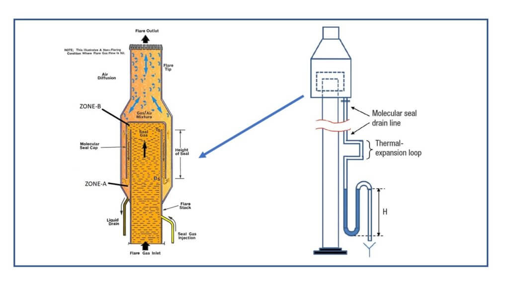
Above figure shows a labyrinth type of seal and its cut-away view. This seal is installed below the flare tip and connected to both the stack and the tip through flanged joints. The labyrinth seal hinders the flow of air into the stack whether the stack gas is lighter or heavier than air. Assuming no purge gas is used and the gas in the stack is lighter than air, the atmospheric air enters zone A due to gravity. However, the air is trapped in Zone B because it is heavier than the gas in this region. Atmospheric air can penetrate Zone B only through molecular diffusion. If the gas in the stack is heavier than air, the atmospheric air cannot penetrate Zone A due to its gravity, except by molecular diffusion. Because it functions on the basis of molecular weights different from air (heavier and lighter), this type seal is frequently referred to as a “Mole Seal”.
The water drain from the labyrinth seal must be looped at grade to provide a 10 feet (3 meters) seal or two times the maximum operating pressure at the base of the stack, whichever is greater. The drain is piped to the knockout drum. A water supply must be available to maintain the water seal level.
In general, the baffle seal costs less than the labyrinth seal because of its simple construction and light weight. Less structural support is required for the baffle seal than for the labyrinth seal.
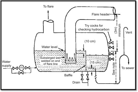
A water seal in a drum is to be provided near the stack or at its base and is to be used in combination with a gas seal just below the stack tip. The gas seal reduces the quantity of purge gas required. Purge gas is required for all systems. In addition, a liquid seal, flame arrestor, or gas seal must be provided.
water seals for flare system
Seal drum-
Seal drums are used to provide a positive seal thus preventing ingression of atmosphere air from flare stack to the flare header. The reason for this seal is to prevent, as much as possible, the development of a combustible air/hydrocarbon mixture and thus prevent flashback in the flare system.
Water seal drums serve as backup to the purge gas system. However, they may also be used to divert flow during normal plant operation to a vapor recovery system or small relief flows to a ground flare. Any larger streams would discharge to an elevated flare with purge gas being introduced downstream of the water seal drum.
The water seal drum is often a vertical vessel installed at the base of a flare stack. In this instance, the drum also provides structural support for the flare stack. The water seal may also be provided in a vertical or horizontal drum separate from the flare stack or ground flare. The decision to select a horizontal or vertical seal drum should be made on the basis of the total installed cost. Large drum diameters will lead to the need for field fabrication.
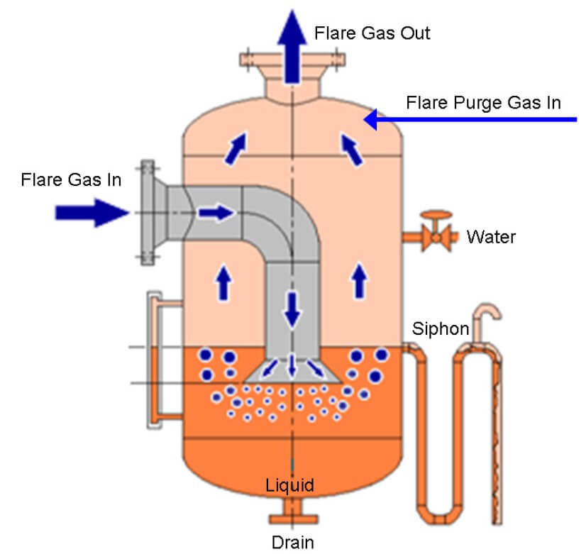
Above figure shows a vertical water seal drum. The water level in the drum is maintained by a constant supply of water. The relief gas inlet pipe is projected into the drum and immersed in the water to form a positive seal. Water from the drum is normally discharged to the oily water sewer system The drum may require provisions for skimming hydrocarbon liquids from the surface of the water. Removal can be either on a continuous or an intermittent basis.
Nasser Zoghaib
Useful Article
Light Yagami
Very nicely explained
sa
Thank you sir. It’s very useful . Please provide more like this,
MS
Hello. Considering intermittent manual skimming of a couple of hundred liters from the Seal Drum (after a relief event, after the flare header cools down), what’s the typical disposition for the skimmed HC liquids? the oily sewer?
sachin.pajwani
Very Crisp and brief intro on flare system