THIS IS PART- Ⅲ OF A SEVERAL PARTS ARTICLE SERIES ON FLARE SYSTEM; CLICK HERE FOR PART-Ⅰ; CLICK HERE FOR PART-Ⅱ.
Flare tip is a large burner or arrangement of smaller burners fitted at the end of flare risers to safely ignite and burn all discharge of flare gas.
Types of flare tip
Flare tips are normally proprietary in design and always evolving so it’s hard to categorize all of them effectively, still some designs are used extensively. Some of which are discussed below.
Open pipe flare tip
This is the simplest type of flare tip consisting of a cylindrical fabrication from which the gas exists, it has a flange at its lower end that in turns connect with the flare riser pipe flange. This design although are very robust and reliable, they are used where smoke is allowed or the gases to be flare do not produce smoke such as methane, hydrogen, hydrogen sulfide and carbon monoxide.
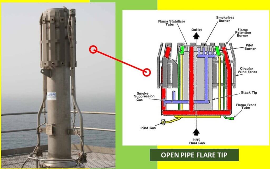
The main body of open pipe flare tip consists of a single pipe, wind deflectors, and flame stabilizers. A purge reduction seal is also included just above the main gas inlet flange and presents a physical barrier to back-flow of air at the inner tip wall. Continuously operating pilot burners are attached to the periphery of the flare tip to ignite the flared gas.
Open pipe flare tip can be used with steam injection, which reduces the smoke emission and radiation levels or it can be used with high pressure gas injection which improves the air gas mixing at the root of the flame.it is also possible to combine high pressure gas injection and water or steam injection in a single pipe flare tip to further reduce thermal radiation levels.
Air assisted flare tip
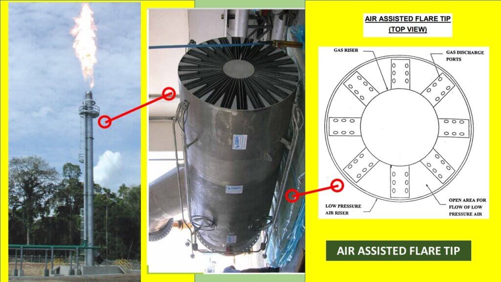
This tip achieves clean combustion through the injection of primary air into the base of the flame with the help of an electrically driven fan/blower located at grade. Combustion efficiency of flared gas is increased by installing air blower which will reduce smoke formation. Air assisted flare tip incorporates a design that splits the waste gas stream into several smaller streams at the top of the flare to increase the gas / air contact surface area and promote better mixing. Forced air from the blowers and gas from the flare header are routed separately from the base of the flare stack to the top of the flare. At no point do the air and gas mix prior to leaving the flare tip, ensuring the safety of the system. These flares are limited in the relief duty which can be handled, because of air mixing and stack diameter limitations. Below is a short video of an installation with air assisted flare tip during operation.
Multi tip flares
Instead of a single burner (e.g. as in open pipe flare tip) the use of multiple, small diameter burners provides improved mixing by splitting the gas and air into smaller units. This improved mixing reduces the mixing path and results in a shorter, broader, flame. The more efficient combustion of multiple tips results in lower smoke emissions and radiation levels than a comparable single tip. This also reduces platform radiation levels and the length of the flare supporting structure.
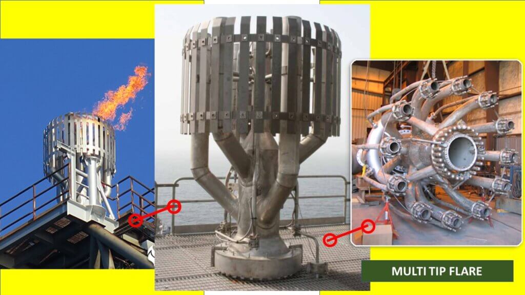
These kinds of flares are used for HP flare application. The main body consists of a central pipe with a number of sonic discharge arms usually between 4, 6 or 8. Each arm has a sonic discharge nozzle fitted. The nozzles provide reliable stabilization of the flame at all flows and also ensure efficient operation, reliable flame ignition and elimination of flame lift at high gas discharge velocities and high winds. The nozzles have a series of lugs behind which a number of gas bleed holes are drilled. This allows some of the gas to escape the nozzle and effectively multiplies the pilot heating power considerably and greatly contributes to flame stability across all operating and atmospheric conditions.
The flare tip is normally fitted with pilots manufactured in heat resistant steel, incorporating a nozzle designed for maximum pilot flame stability, an inspirator (air drawing device) assembly for regulating the air and gas mixture to the pilot and the igniter which fits into the nozzle directly. Below is a short video of an installation with multi point flare tip during operation.
Coanda flare tips
The tendency of a fluid discharging from a jet or a slot to adhere to an adjacent convex surface, entertaining the surrounding fluid is called the Coanda effect. A simple experiment which batter explains it, can be seen below.
In a coanda burner this above effect is used to allow the gas film to be in contact with the atmosphere; this results in the tip having a high ratio of perimeter to area and hence the advantages of improved air entrainment. This effect has been applied on high pressure gas flare tips in many variations.
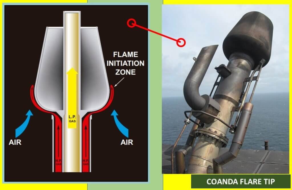
One variation of coanda flare tip has a tulip-shaped tip on the top of a concentric stack. The high-pressure gas is fed into the outer annulus of the stack and emerges at sonic velocity from the annular slot. The hollow tulip shaped tip may have a low-pressure gas flowing through its core. As the high-pressure gas follows the surface of the tulip it entrains sufficient air to burn not only itself but also up to about one-third of its volume of low-pressure gas fed into the flame from the center of the stack.
Coanda burners have the benefits of reduced smoke generation, ease of ignition (even under sudden venting), the ability to burn gas and entrained liquid mixtures and reduced radiation levels. The operation of this type of burner does, however, require high pressure gas. In addition, higher noise levels are experienced than with similar sized pipe flares. There is normally only a limited optimum flow range.
High Velocity Tips
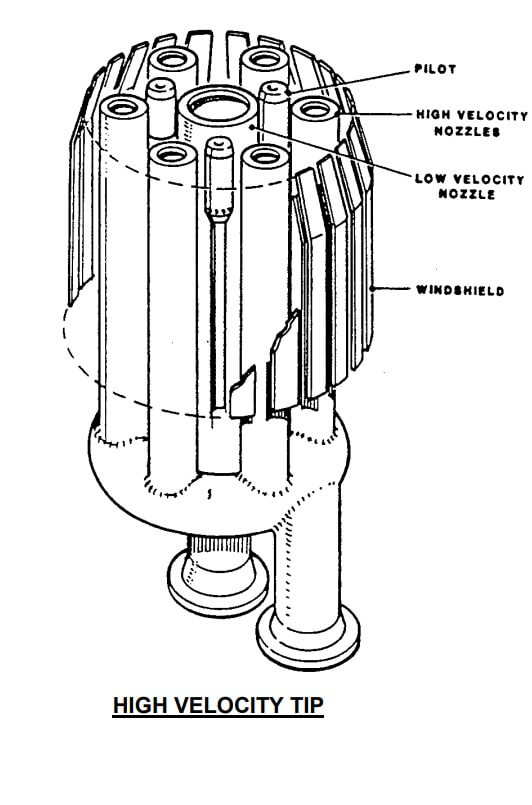
The use of very high and sonic velocity gas jets at the flare tip improves air entrainment compared to similar conventional pipe flares. The use of multiple jets and/or a low-pressure jet ensures stabilization of flame under these high velocities. The improved air entrainment as a result of the turbulence in the high velocity gas jet reduces smoke formation and thermal radiation.
Flare pilot burners & pilot ignitors
On flares, Environment Protection Agency (EPA) regulations requires a continuous flame to be present. This is provided with help of continuous pilot burners designed for reliable ignition as well as stability. These pilot burners are positioned around the outer periphery of the flare tip.
The pilot burners have to be ignited and an ignitor is used for that. The function of the ignitor is to ignite the pilots, which in turn light the flare burner. Most flare tips have a minimum of three pilots equally spaced on the circumference of the tip. These pilots are equipped with wind shields so that the most severe wind cannot blow them out. Some common type of ignitors furnished by vendors are discussed below.
Electronic ignitor
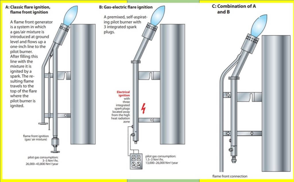
Electrical ignitors provide ignition of flare gas, pilot monitoring and automatic reignition on loss of pilot. The traditional method of lighting with a flame front ignitor (see below) requires several steps. Electronic ignitors eliminate the need for flame front generation by introducing a spark within the pilot nozzle. These systems are available either for manual or automatic operation. In manual operation, ignition is initiated via a push-button after the pilot flame is observed to be out. Automatic systems detect the presence of the pilot flame via induced currents between the ignitor and ground. If the system detects the pilot is lost, a spark is automatically released to reignite the pilot.
Pressure ignitor (Flame front ignition)
Each pilot has an ignitor pipe adjacent to it. a gas/air mixture is introduced at ground level and flows up a one-inch line to the pilot burner. After filling this line with the mixture, it is ignited by a spark. The resulting flame travels to the top of the flare where the pilot burner is ignited. Also, the flame front is split to ignite all the pilots.
A pressure ignitor can be located as far as 1,500 m from the pilots. A vendor must be consulted to confirm this maximum distance. Typically, a pressure ignitor is located as close to the flare stack as practical, but outside the safe radius circle.
flame-front-generators-and-ignitorsAbove figure shows how the FFG generators and the pilot burner/ignitor spools work together. These are basically vendor specific items so a lot of proprietary design and variant exists according to requirement.
Pilot gas inspirator
Pilot gas inspirator are required for mixing a fuel gas with atmospheric air in a precise ratio to regulate burn characteristics. Here only the pressure of the fuel gas is used to draw in and mix the air. An inspirator is a device, similar to a venturi tube and an orifice plate.
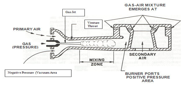
In an inspirator there are two tubes. The first is a fuel gas pipe with an orifice at the end where the gas comes out. Then in front of this there is another section of tubing with a larger diameter that the gas blows into. Usually (but not always) this second piece of tubing is tapered so that it starts getting narrower downstream from the orifice. Then, at a certain point, it stops getting narrower and either straightens out or starts getting larger again. This gives the fuel and air time to mix. The fuel/air ratio is determined by the ratio of the diameter of the orifice to the diameter of the mixing tube.
Pilot Monitoring
An alarm system warns that a pilot at the burner is out. For flame front/pressure ignitors, this consists of a chromel-alumel thermocouple installed at the base of each pilot and connected to a temperature alarm switch. Loss of flame temperature then actuates an alarm switch. Electronic ignitors can be installed with a self-contained monitoring system. This pilot monitoring should be installed for each flare.
References:
“Inspirator” Retrieved, from https://en.wikipedia.org/wiki/Inspirator.


Tejas salian
Interested in cold flare system for our forthcoming PVC plant at Dighi, Maharashtra.
KIm Gwang-Dong
Dear Sir,
Could you please explain something about “Muffle Slice” for flare stack in refinery?
Thank you very much for your help in advance.
thepipingtalk
Hey, Question is open to visitors to answer.