Introduction:
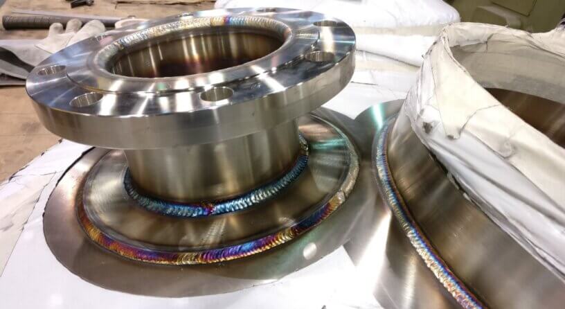
Standard fittings like a tee, weldolet, sockolet , half couplings are generally used when there is a need to take branch out from header. Still at some places either standard size fittings are not available or too costly to put in the line. At these places, the design of branch connection shall be according to guideline provide by the respective piping code para 304.3. Below is Para 304.3.2 quoted from B31.3-
304.3.2 Strength of Branch Connections. A pipe having a branch connection is weakened by the opening that must be made in it and, unless the wall thickness of the pipe is sufficiently in excess of that required to sustain the pressure, it is necessary to provide added reinforcement. The amount of reinforcement required to sustain the pressure shall be determined in accordance with para. 304.3.3 or 304.3.4. There are, however, certain branch connections which have adequate pressure strength or reinforcement as constructed. It may be assumed without calculation that a branch connection has adequate strength to sustain the internal and external pressure which will be applied to it if
(a) the branch connection utilizes a listed fitting in accordance with para. 303.
(b) the branch connection is made by welding a threaded or socket welding coupling or half coupling directly to the run in accordance with para. 328.5.4, provided the size of the branch does not exceed DN 50 (NPS 2) nor one-fourth the nominal size of the run. The minimum wall thickness of the coupling anywhere in the reinforcement zone (if threads are in the zone, wall thickness is measured from root of thread to minimum outside diameter) shall be not less than that of the unthreaded branch pipe. In no case shall a coupling or half coupling have a rating less than Class 2000 per ASME B16.11.
(c) the branch connection utilizes an unlisted branch connection fitting (see para. 300.2), provided the fitting is made from materials listed in Table A-1 and provided that the branch connection is qualified as required by para. 304.7.2.
Summarizing it
(1) Standard fittings built according to asme code like ASME B16.9, ASME B16.5, MSS SP codes are already qualified so these fiitings are inherently termed as adequate.
(2) Unlisted/non standard Branch connection can also be termed as adequate if it satisfies para 304.7.2 which is quoted as it is below-
(a) extensive, successful service experience under comparable conditions with similarly proportioned components of the same or like material.
(b) experimental stress analysis, such as described in the BPV Code, Section VIII, Division 2, Appendix 6.
(c) proof test in accordance with either ASME B16.9, MSS SP-97, or Section VIII, Division 1, UG-101.
(d) detailed stress analysis (e.g., finite element method) with results evaluated as described in Section VIII, Division 2, Appendix 4, Article 4-1. The basic allowable stress from Table A-1 shall be used in place of Sm in Division 2. At design temperatures in the creep range,
additional considerations beyond the scope of Division 2 may be necessary.
(e) For any of the above, the designer may interpolate between sizes, wall thicknesses, and pressure classes, and may determine analogies among related materials.
(3) If there is a non standard connection usually what we fabricate on site like pipe to pipe branch connection, it need a calculation of strength as per Para 304.3.3 which will tell of the additional requirement of reinforcing pad and if strength of branch fulfils the criteria of code. Readers can follow the code B31.3 for this, as what’s written in code is pretty straight forward and in code itself they have given how to calculate these with an example on appendix-H. Nonetheless we will try to depict the procedure and calculation here with an example.
Branch strength calculation procedure:
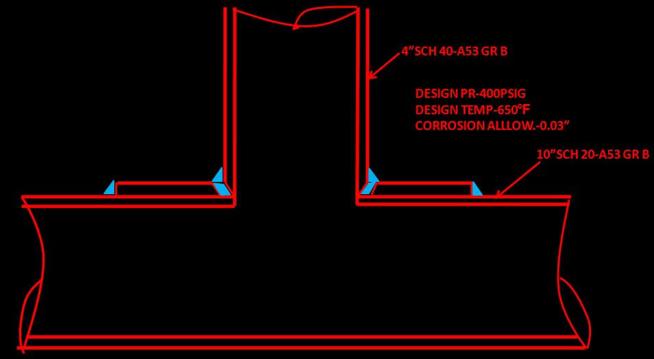
We will calculate if reinforcement is required, and its size if required for a branch connection with details as provided in below Fig-1.

Dh= O.D of header or run pipe in mm = 273.1
Db= O.D of branch pipe in mm = 114.3
Tb= Nominal thickness of branch pipe in mm = 6.02
With negative 12.5 mill tolerance it is = (1-(12.5/100)) X 6.02 = 5.26
Cb= Corrosion allowance for branch pipe in mm = 0.76
Th= Nominal thickness of header pipe in mm = 6.35
With negative 12.5 mill tolerance it is = (1-(12.5/100)) X 6.35 = 5.55
Cb= Corrosion allowance for header pipe in mm = 0.76
Tr = minimum thickness of reinforcing ring or saddle in mm = 6mm***
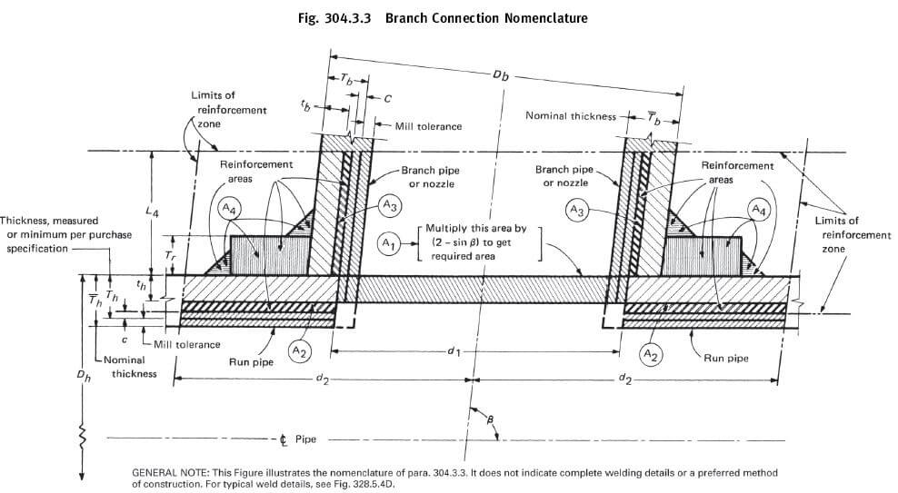
tc = throat dimension of fillet weld = 0.7*Tb or 6 mm whichever is less = 4.214. For other nomenclature you can also refer drawing from code given below .

First we have to calculate area available for reinforcement. A branch is deemed fit if area available for reinforcement is greater than area required for reinforcement. If area available for reinforcement is less than the required reinforcement area, we have to add reinforcement saddle with proper thickness and recalculate the area, this time with increased area until it satisfies the above said condition.
A1 = Required Reinforcement Area for branch connection under internal pressure is.

Where th= pressure design thickness for run pipe

d1= effective length removed from pipe at branch

so putting all values in equation for A1 we get

A2 = Area resulting from excess thickness in the run pipe wall

Where d2=half width of reinforcement zone d2

So putting values in equation

A3 = Area resulting from excess thickness in the branch pipe wall

Where L4=height of reinforcement zone outside of run pipe.

***Please note in above equation we have put thickness of reinforcing ring /saddle Tr as 6 mm . when you calculate 1st time value of Tr shall be 0.
Where tb= pressure design thickness for branch pipe

So putting values in equation

A4 = Area of other metal provided by welds and properly attached reinforcement.
A4= (A5+ A6+ A7)
Where A5=reinforcing area in reinforcement ring in mm2

Where Lr = length of reinforcement pad measured along the run pipe in mm

Putting values in equation A5=

A6=weld reinforcing area without ring in mm2=

A7=reinforcing area at ring in mm2 =

Where lw= leg dimension of weld at reinforcing ring =


dw= weld dimension at ring used in calculation

So putting values in equation A7=

And summing up A5,A6&A7

Total area available for reinforcement =

So in our case total area available for reinforcement (859.38) > area required for reinforcement (335). So the branch is fit.
*** We have taken reinforcement pad thickness as 6 mm for easy of explanation. In real first you have to calculate without a reinforcement saddle to know if reinforcement saddle/pad is even required. In that case value of Tr thickness of pad is 0, value of A5 and A7 will also become 0.
Let us just see with Tr = 0 what value we will get
Total area available for reinforcement =

In this case total area available for reinforcement (280.93) < area required for reinforcement (335). So the branch is unfit and we need to add reinforcing pad/saddle.
Now that you know branch is unfit you can assume a Tr value most probably the same thickness as the run pipe as we had done before (i.e 6mm) and recalculate until area available becomes > area required.
Once it is fit. You can calculate
From length of reinforcement Lr you can calculate size of reinforcement ring by below formula = (lr-Db)/2 = (210-114.3)/2 = 47.85~50
So size of your reinforcement pad becomes 50mm wide ring X 6 mm thk.
A lot of calculators are available in organization and on web for doing all this, one such is presented here, with the same calculations we have done so far.
click here to download branch reinforcement pad calculation excel


Naufal Anshari
Thank you for your sharing, I want to know where you get the A4 formula?, because on ASME B31.3 A4 is only statement “Area of the other metal provided by welds and properly attached reinforcement”
thepipingtalk
Dear Anshari, U are correct-AS per Asme A4 is 2 x 1/2 x weld leg dim2. i also have noted the same please see the *** note near the end of post. so in our equation A4= A5+A6+A7: initially we have to calculate without pad so A5 & A7 becomes 0 thus A4= A6= weld leg dim2..that is same as ASME.
sorry for the confusion. A5 and A7 comes into play when we have check the strength, once certain thick saddle/ring is added. A5 And A7 formulae given here are geometrically calculated, i have taken it from a standard company calculation sheet.