

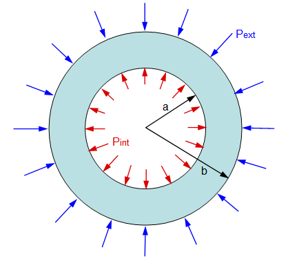
When we say internal pressure thickness design we have to deal with the tensile properties of the material, where the pressure is trying to expand the material from inside and trying to tear it into two. With external pressure the opposite happens. The pressure is trying to compress the material to squeeze it together.
Steel has very similar properties in tension and compression. So you may think external pressure on pipe will never be as much as internal pressure, and as we are calculating thickness of pipe for internal pressure, this will take care of the external pressure as well. This is wrong because in compression the failure can occur well below the yield point.
“This phenomenon is called buckling where a column/pipe loaded in compression with critical load, the column/pipe will fail before the load that would actually required failing in tension.”
Jacketed pipes, pipe deep inside sea, vacuum piping, internal piping inside vessel are some of the instances where pipe experience this phenomenon of external pressure. External pressure thickness of pipe/tubes/cylindrical shells are calculated according to- ASME SECTION VIII DIV-1 UG-28. There are two separate procedure specified for calculating minimum required thickness, for Do/t ≤ 10 and Do/t >10. In this article we will discuss about the first one which is commonly applicable for pipes with an example.
We will calculate the external pressure design thickness for 6” NB pipe having external pressure 250 psig at 750°F , Material of construction is A312 TP 304L , corrosion allowance – nill.
There are 4 steps:
STEP-1
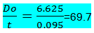
Find Do/t where Do = outside diameter = 6.625 in , t = thickness in corroded condition.
For 6” ss pipe the minimum commercially available thickness is sch-5s = 0.109”. mill tolerance is ±12.5%, so in calculation we have to use the least thickness we will get considering negative 12.5% mill tolerance. So t = 87.5% of 0.109” = 0.095 in.
STEP-2
Calculate L/Do where Do = outside diameter = 6.625 in
L = total length between two end support of pipe i.e maximum unsupported span. Consider length of straight pipe with a flange on one end of the spool and a valve some distance away. That distance between the flange and valve would be the length under consideration. In the absence of any stiffener similar to the valve or flange, stiffener ring can be added around pipe.
For the sake of calculation we will use length as 330 in (8300 mm approx).
For L/Do greater than 50 enter the chart at a value of L/Do = 50 and for values less than 0.05 enter the chart at a value of L/Do = 50.
STEP-3
Determine factor A form Fig. G sub part 3 of section ii, part D (geometric chart for component under external or compressive loading). Find out factor A in the graph by moving horizontally to the line for value of Do/t. interpolation may be done for intermediate values of Do/t. from this point move vertically downward to determine value for Factor A (see fig. 1). There is also a tabular chart available in with values from the graph which you can use.
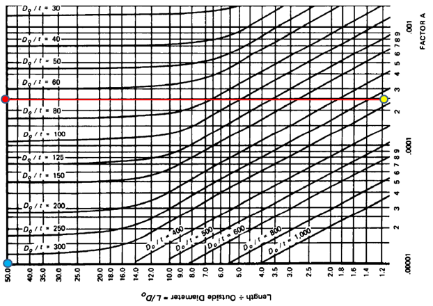
In our case factor A = 0.00025 from fig. G.
STEP-4
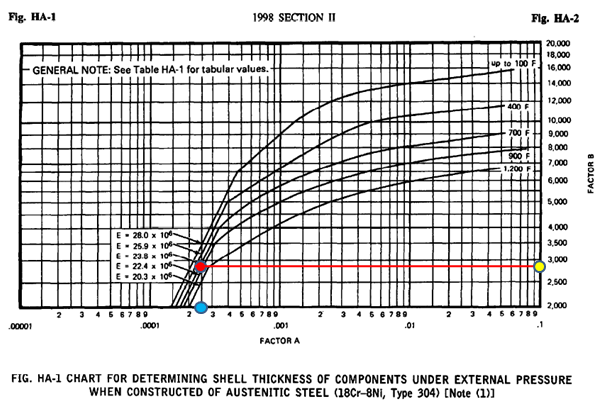
Using the values of A calculated in step 3, enter the applicable material chart in subpart 3 of section ii part D. as our material of construction is TP 304L we have to see FIG. HA-1- which is chart for determining shell thickness of component under external pressure when constructed from austenitic steel.
Move vertically to an intersection with the material/temperature line for the design temperature. Interpolation may be done for intermediate temperature. and then move horizontally to right to read the value of Factor B.
As shown below Fig. 2 in our case we get value of Factor B =2750
In case the values of A falls to the right of the end of material temperature line, assume an intersection with the horizontal projection of the upper end of the material temperature line and then move horizontal to right end to read value of Factor B. see refer next step When Factor A falls left hand side refer STEP-6
STEP-5
Calculate maximum allowable external working pressure (Pa)
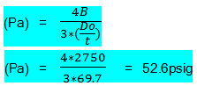
This shows the allowable external pressure on pipe is only 52.6 psig where as we have to design the pipe to sustain 250 psig. So repeat again from step 1 with next available thickness.
With thickness 6” sch 40 = 0.28 thickness you will get Do/t=27.04, L/Do=50, Factor A = .0018, Factor B= 6000
(Pa) =(4*6000/3*27.04) = 295.8 psig which is > 250 psig.
So our calculated external pressure design thickness is 6” sch 40=0.28 inch thick pipe, which will be safe for an external pressure of 250 psig.
STEP-6
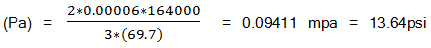
When Factor A falls left hand side of the curve Calculate maximum allowable external working pressure (Pa) by below formulae
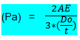
For example if A=0.00006, E from graph up to 750°F=23.8 x 10^6 PSI = 164.0 X 10ˆ3 mpa.
Taufiq
Can u give an example for interpolation of Factor A and B?? Thanks a lot
Shah Hussain
Too nice and fine work elaborated with systematic manner