Introduction:
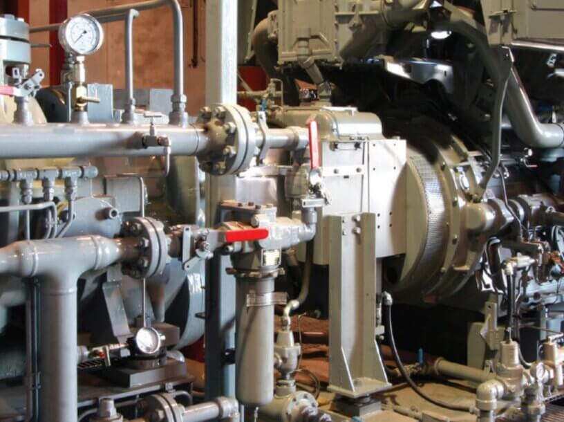
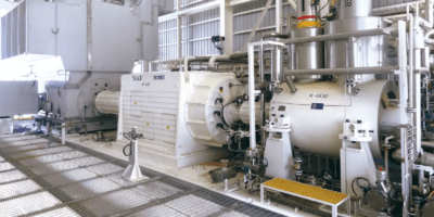
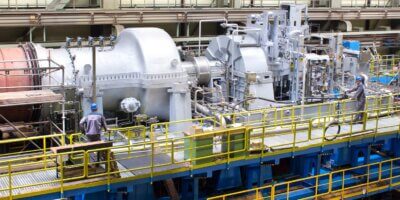
Lube oil console are used in turbo machinery packages for e.g. steam turbine, gas turbine, compressor packages etc. for supplying clean and cool lubricating oil to the seals & bearings.
Below figure-1 shows a common lube oil system configuration. it consists of a primary and an auxiliary pump which drive lubricating oil throughout the system. The pump drives the lubricating oil from reservoir to cooler and then to filter, then it goes to the respective bearings and flows back to reservoir by gravity to start the loop again.
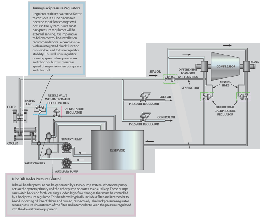
The pumps operate in a primary/auxiliary setup, where the primary pump drives the system pressure to desired condition with the auxiliary pump providing a backup in the event of primary pump downtime or maintenance . The auxiliary pump turns on when the system pressure drops below the optimal condition or it can be started manually by the user in order to turn off the primary pump case of scheduled maintenance.
Why we need Back Pressure valves in lube oil system:
As we have discussed earlier the primary and auxiliary pump can switch back and forth between them. At times while the primary pump is running, the auxiliary pump is started, causing both pumps to act together for sometime before primary pump is switched off and maintenance work performed on it. For that time span where both pumps act together there is a sudden high flow in the system and there is a need to regulate this pressure so that it does not damage the system. As you can see in fig:1 there is safety valves to protect the pump and vent to the reservoir. But it’s wrong to think that these safety valves will protect the system by popping up when there is over pressure. It’s so because ideally these safety valves are so designed that it should not lift during standard operation. Here safety valves acts as last line of defence and for large swings in flow that results from pump switching, commonly a direct operated back pressure regulator tied into the pump header is used which senses pressure changes and adjust flow accordingly. Obviously the location from where it senses the pressure and regulates the pressure is also important.
The proper operation of turbo machinery bearings relies on clean lubricating oil appropriate for the application and efficient transfer of heat out of the bearings. Because the lube oil filter and heat exchanger see a considerable pressure drop, it is common for the back pressure regulator to use an external line which senses pressure downstream of the heat exchanger and filter and keep constant, controlled pressure supplied to the downstream bearing and seals.
How a Back Pressure valves works:
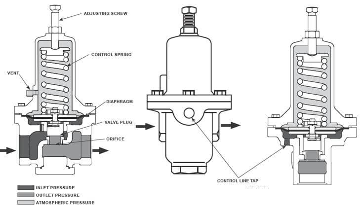
Relief or back pressure valves respond to changes in upstream pressure or the pressure which it senses from the external control line. First the desired pressure is set by adjusting screw present at top of the valve body. Pressure changes register under the diaphragm (see Figure 2) through a registration hole in the valve body or through an external control line. When this pressure increases above the spring setting, the pressure underneath the diaphragm overcomes the spring compression. This causes the valve plug to move away from the orifice. The flow path through the valve is open and excess pressure is vented. When upstream pressure drops below set point, the valve closes.
A simplified animation available is presented here for understanding, please note it’s without external control line .
How to control speed of response for back pressure valve:
Due to pump on and off the system can see instantaneous increase or decrease in header pressure. In direct operated valves there is no external sensing, the valve senses the pressure of the upstream line connected to it and use this as the reference pressure to control. This type is used to respond rapidly to this pressure fluctuation. The back pressure valve responding to this spontaneous highs and lows, will quickly position itself to suit the upstream pressure. This quick action though needed, it may lead to large pressure swings leading to system shutdown or vibration.
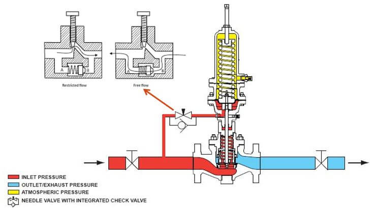
To avoid above said system shutdown and vibration originating from rapid response, sometimes a needle valve with integrated check function is used to tune the regulator response speed, see fig-3. The needle valve is installed in the sensing line of the back pressure regulator. By controlling the needle valve opening we can control regulator speed of response. For e.g if the needle valve has less opening it will take more time for the fluid to pass through and build up exact pressure on the diaphragm and if the needle valve has more opening it will take comparatively less time to build up the exact pressure. The integrated check function allows for unrestricted return flow from the valve Diaphragm plunger. This is needed as the sudden shutdown of one pump requires the regulator to immediately close the valve preventing sudden loss of header pressure thus restricting fluid flow to drain/reservoir.